Numerical controller with display of a preview when the parts program is changed

a numerical controller and preview technology, applied in the field of numerical controller operation, can solve the problems of workpieces which are not correctly produced, restricted set of commands available, and inability to program free-form processing activities, etc., and achieve the effect of simplifying the intuitive appreciation of the details of the situation

Inactive Publication Date: 2015-10-08
SIEMENS AG
View PDF22 Cites 5 Cited by
  • Summary
  • Abstract
  • Description
  • Claims
  • Application Information

AI Technical Summary

Benefits of technology

[0030]According to another advantageous feature of the present invention, the data and the changed data may include additional path data items, which specify a path of the tool which is processing the workpiece. In this case, the numerical controller inserts the path into the image and the amended image. The result is a simpler intuitive appreciation of the details of the situation for the user.
[0031]Advantageously, the numerical controller may also insert into the image the tool, and move it along the path. This approach improves still further the intuitive appreciation of the details of the situation.
[0032]According to another advantageous feature of the present invention, in response to control commands input by the operator, the numerical controller may stop and then resume the movement of the tool. Alternatively or additionally, the numerical controller may adjust the speed with which the tool is moved in the image as a function of control commands from the operator. By these two measures—in particular by the combination of the two measures—it is possible to investigate especially precisely any critical processing operations.
[0033]When it is possible to stop the movement of the tool relative to the workpiece, the numerical controller may advantageously receive from the operator a location along the path, and when the tool is stopped in the image it is positioned in the location received from the operator. By this means it is possible to specify in a simple way the location at which the tool is stopped in the image. The location can, in principle, be prescribed by the operator in any arbitrary way. It is especially simple if the operator marks a particular location, using a cursor or a pointer or suchlike, in the image into which the path is inserted, and either the marking as such causes the tool to be stopped at this location, or after the relevant location has been marked the tool is stopped by a separate stop command.
[0035]According to another advantageous feature of the present invention, the numerical controller may process an real workpiece by executing the parts program and the numerical controller may move the tool in the image along the path which has been inserted into the image, in correspondence with the actual processing of the workpiece. By this means, the operator can observe in a simple way via the operator interface the processing of the workpiece, corresponding to its actual progress.

Problems solved by technology

However, only a significantly restricted set of commands is available via the operator interface of the numerical controller.
It is not possible to program free-form processing activities by means of the restricted set of commands which can be generated via the operator interface of the numerical controller.
However, unlike a free-form processing activity, the parts program generated by the CAM system does not directly contain the sequence of the associated individual control commands for the positionally—and rotation-speed-regulated axes of the production machine, but instead a sub-routine call for the cycle together with the appropriate parameterization.
A consequence of this can be that the execution of the parts program by the numerical controller results in workpieces which are not correctly produced.
If the same cycle is used repeatedly with different parameters (for example: the same contour is to be produced at different places on the workpiece), it can in addition happen that an incorrect cycle is parameterized by mistake.

Method used


Image

  • Numerical controller with display of a preview when the parts program is changed
  • Numerical controller with display of a preview when the parts program is changed
  • Numerical controller with display of a preview when the parts program is changed

Examples


Embodiment Construction

[0055]Throughout all the figures, same or corresponding elements may generally be indicated by same reference numerals. These depicted embodiments are to be understood as illustrative of the invention and not as limiting in any way. It should also be understood that the figures are not necessarily to scale and that the embodiments are sometimes illustrated by graphic symbols, phantom lines, diagrammatic representations and fragmentary views. In certain instances, details which are not necessary for an understanding of the present invention or which render other details difficult to perceive may have been omitted.

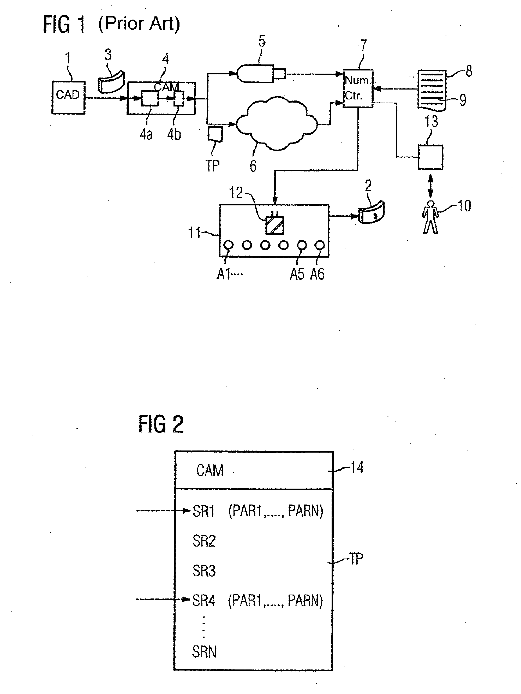
[0056]Turning now to the drawing, FIG. 1 shows a conventional network of several items of equipment, wherein a workpiece 2 which is to be produced is first specified by means of a CAD system 1. A (purely geometric) specification 3 of the workpiece 2 is passed over to a CAM system 4. The CAM system 4 generally incorporates a CAM processor 4a and a postprocessor 4b. Using the ...


PUM


Abstract

A numerical controller executes a parts program controlling a production machine. An operator selects via a selection command a program instruction in the parts program that is parameterized with at least one parameter. The program instruction is converted into a movement of a tool processing a workpiece. Information identifying the program instruction is communicated to a CAM system which then returns data specifying a three-dimensional geometry of the workpiece commensurate with the selected program instruction and determines an image of the workpiece. The operator can change the parameters and hence also the image. Any changes of a parameter are communicated to the CAM system which then determines a changed image of the workpiece and outputs the changed image to the operator. A modified parts program corresponding to the changed program instruction can be stored upon receipt of a storage command from the operator.

Description

CROSS-REFERENCES TO RELATED APPLICATIONS[0001]This application claims the priority of European Patent Application, Serial No. 14163149.9, filed Apr. 2, 2014 pursuant to 35 U.S.C. 119(a)-(d), the content of which is incorporated herein by reference in its entirety as if fully set forth herein.BACKGROUND OF THE INVENTION[0002]The present invention relates to a method of operation for a numerical controller, to a computer program for executing the method of operation on a numerical controller, and to a numerical controller with a stored computer program that can be executed by the numerical controller.[0003]The following discussion of related art is provided to assist the reader in understanding the advantages of the invention, and is not to be construed as an admission that this related art is prior art to this invention.[0004]In ongoing operation, numerical controllers conventionally run a so-called parts program. The parts program specifies how axes of the production machine (in par...

Claims


Application Information

Patent Timeline
Patent Type & Authority Applications(United States)
IPC IPC(8): G05B19/4097
CPCG05B19/4097G05B19/4069G05B19/4093G05B2219/36043Y02P90/02
Inventor SINN, CHRISTOFSTOLPER, THILO
Owner SIEMENS AG
Why Eureka
Try Eureka