Dual-band feed horn with common beam widths

a technology of beam width and horn, applied in the field of dual-band antennas, can solve the problems of consuming valuable space on spacecraft, reducing efficiency, and reducing so as to achieve the same angular beam width, reduce the pointing requirement of the antenna system, and narrow the angular beam width

Active Publication Date: 2015-02-17
LOCKHEED MARTIN CORP
View PDF14 Cites 161 Cited by
  • Summary
  • Abstract
  • Description
  • Claims
  • Application Information

AI Technical Summary

Benefits of technology

[0014]This disclosure describes the design of antenna systems and, in particular, feed horns that can transmit and receive signals in two or more widely separated frequency bands within the microwave frequency range. The antenna systems and horns have substantially the same angular beam widths in all frequency bands which reduces the pointing requirement of the antenna system compared to a two-band antenna system that has a narrower angular beam width at the higher frequency band than at the lower frequency band. This is achieved in certain embodiments by the use of slope discontinuities in a smooth-walled conical horn. The diameters and positions of the slope discontinuities are selected to produce TE modes in all frequency bands while producing TM modes primarily in the higher frequency bands and few TM modes at lower frequency bands. The TM modes reduce the efficiency of the horn at the higher frequencies and consequently widen the angular beam widths of the higher frequency bands to match angular beam width of the lowest frequency band.

Problems solved by technology

Higher-level Transverse Electric (TE) fields tend to enhance the efficiency of a horn while Transverse Magnetic (TM) modes tend to reduce the efficiency.
This is due to the lack of feed horns that can efficiently support both uplink and downlink frequencies that are widely separated.
These conventional multibeam satellites require several antenna apertures which consume valuable space on the spacecraft and are relatively expensive due to twice the number of reflectors and twice the number of feed horns required when compared to the dual-band antenna system disclosed herein.
Other conventional multiple-beam satellite payloads, such as AMC-15, AMC-16 and Rainbow, employ dual-band antennas using low-efficiency corrugated feed horns to realize dual-band operation, but have a significantly lower RF performance.
Disadvantages with this approach include increased losses, the requirement of two separate feeds, a FSS subreflector, the complexity and consequent cost of the antenna, and narrow bandwidths.
Disadvantages with this approach include high cross-polar levels due to coaxial modes, strong mutual coupling of signals between low and high frequency bands, and narrower bandwidth of operation.
The TM modes reduce the efficiency of the horn at the higher frequencies and consequently widen the angular beam widths of the higher frequency bands to match angular beam width of the lowest frequency band.

Method used


Image

  • Dual-band feed horn with common beam widths
  • Dual-band feed horn with common beam widths
  • Dual-band feed horn with common beam widths

Examples


Embodiment Construction

[0031]To overcome at least some of the disadvantages of existing dual-band antennas listed above, there is a need for an inexpensive antenna solution that works over two widely separated frequency bands. In addition, it is desirable that the co-polar radiation patterns of the antenna at the high frequency and at the low frequency be substantially the same to simplify the pointing requirements of the antenna system to maintain the communication link.

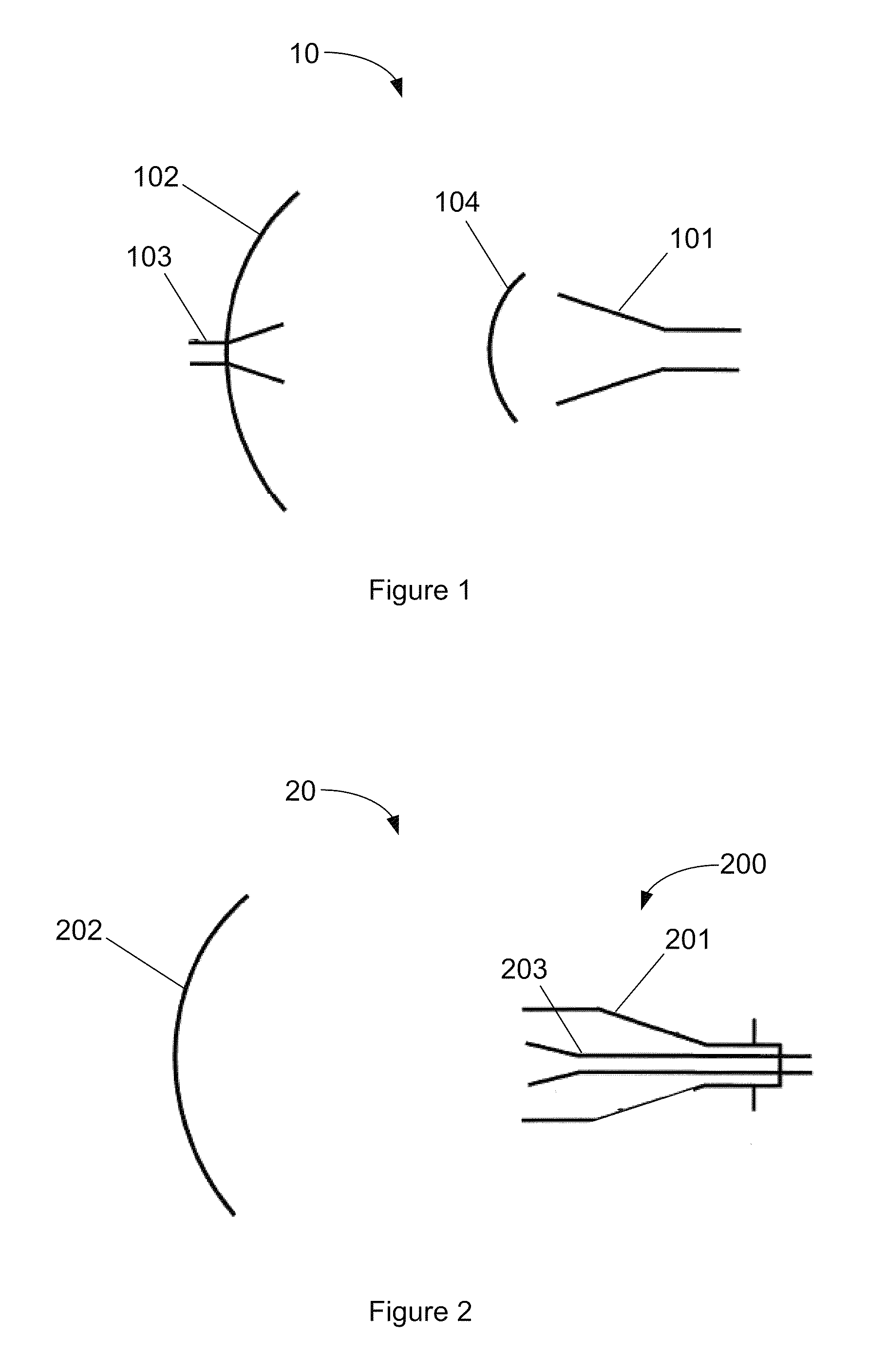
[0032]The present disclosure is made with examples of a single-offset reflector antenna and a Cassegrain dual-reflector antenna, both using a single dual-band feed horn. It will become apparent, however, that the concepts described herein are applicable to antenna systems of other types and configurations.

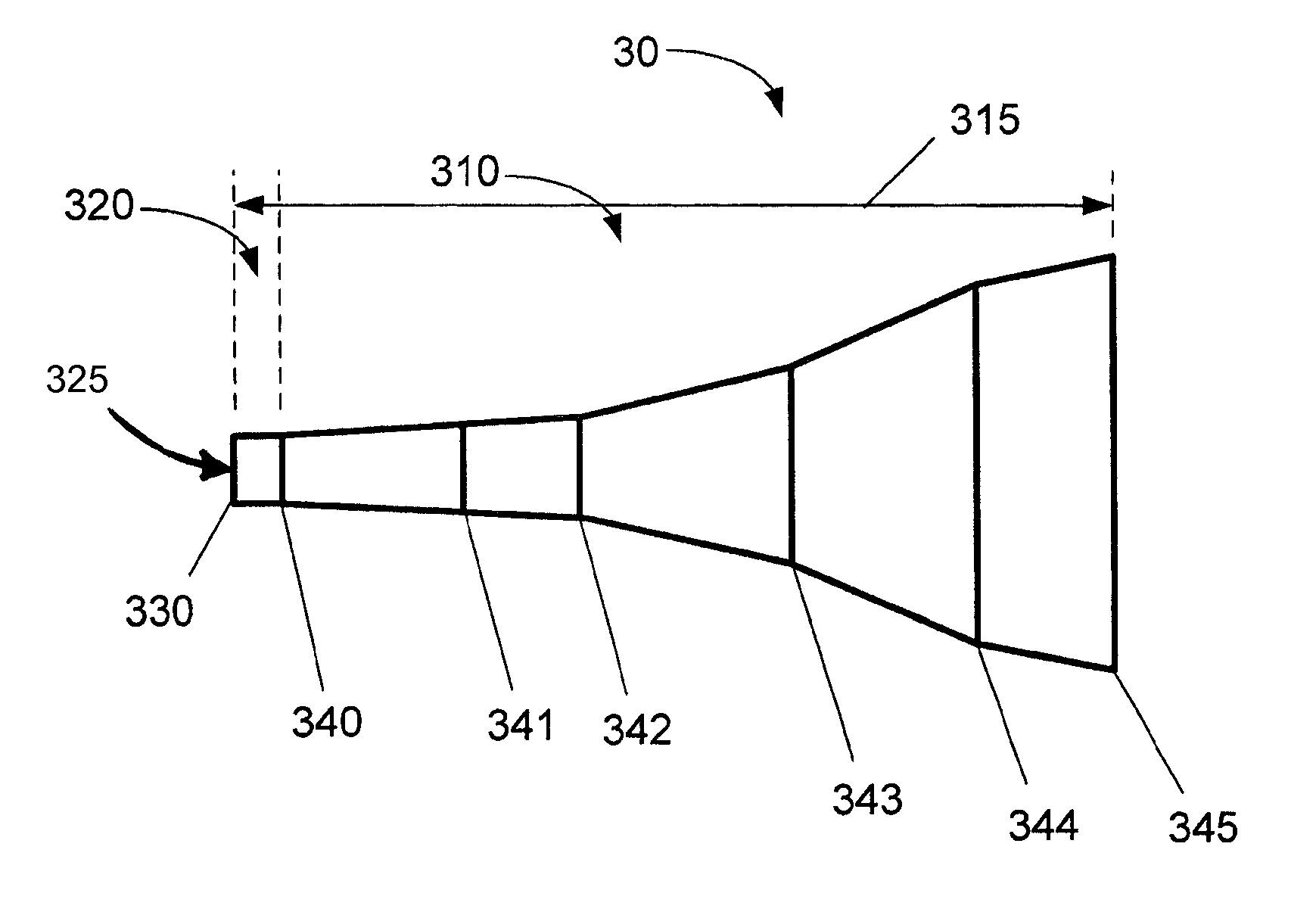
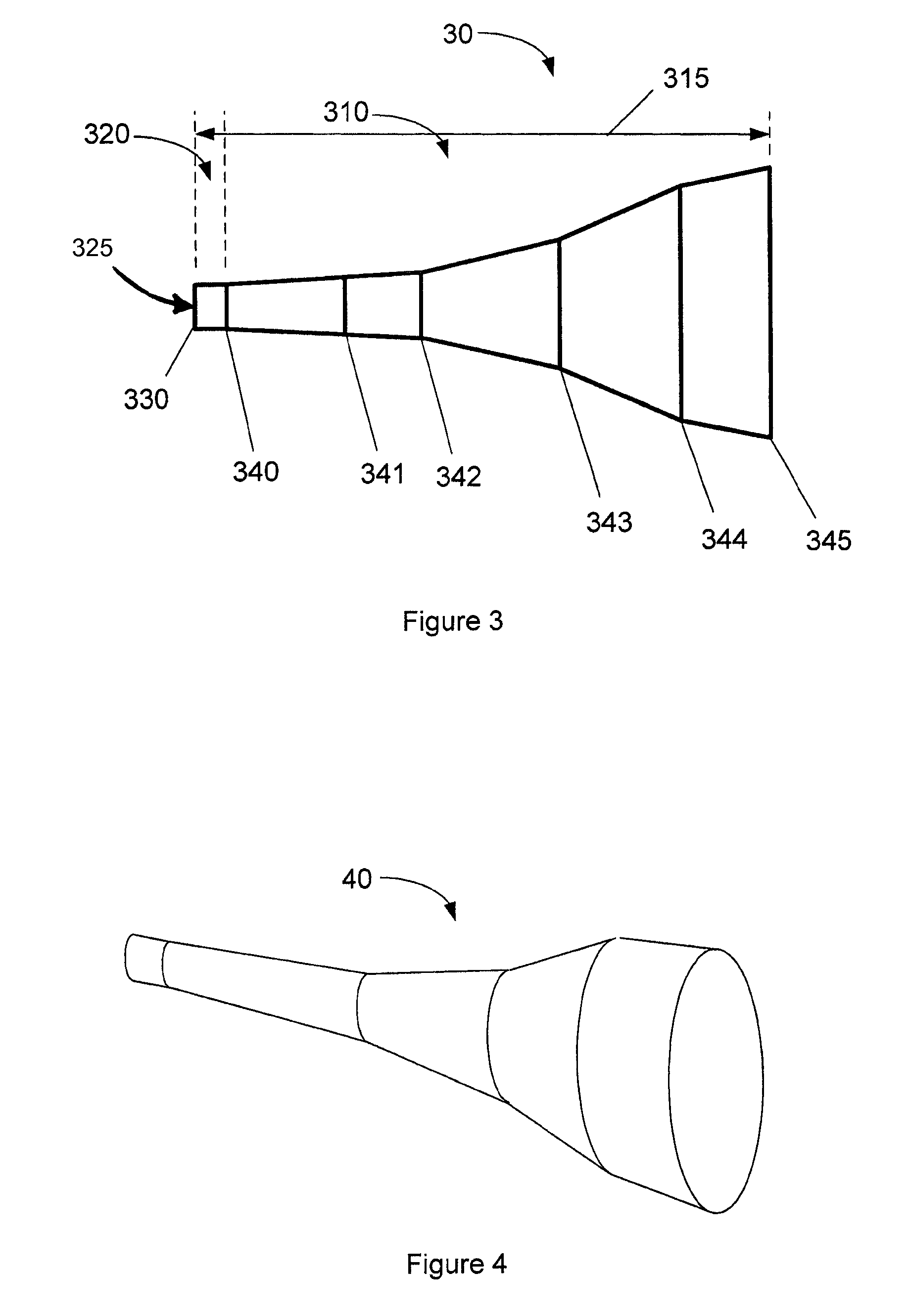
[0033]Horn antennas are frequently used as feed horns in reflector antenna systems. The generation of TE modes in a conical horn was discussed in U.S. Pat. No. 7,463,207 and this nonessential matter is incorporated herein by reference. T...


PUM


Abstract

A dual-band feed horn having a connection surface configured for connection to a waveguide and a first surface coupled to the connection surface. The first surface has a cylindrical surface with a length and a first diameter chosen to propagate TE11 modes for both a low frequency band and a high frequency band. The horn has a bandwidth ratio of the high-frequency band to the low frequency band in the range of 1.6-4.0. The horn also has a substantially conical surface coupled to the first surface at a first slope discontinuity. The conical surface includes multiple surfaces each having a respective slope and coupled to adjacent surfaces by a respective plurality of slope discontinuities each having a respective diameter. The slopes and diameters are chosen to generate primarily TM1,m modes (m=1, 2, 3, etc.) in the high-frequency band and primarily higher order TE1,n modes (n=2, 3, etc.) in the low-frequency band such that the low frequency band and the high frequency band have approximately equal beam widths.

Description

[0001]This application is a continuation of U.S. application Ser. No. 12 / 713,145, filed Feb. 25, 2010, and issued as U.S. Pat. No. 8,514,140 on Aug. 20, 2013, which claims the benefit of U.S. Provisional Application No. 61 / 168,464, filed Apr. 10, 2009, all of which are incorporated herein by reference in their entirety.STATEMENT REGARDING FEDERALLY SPONSORED RESEARCH OR DEVELOPMENT[0002]Not applicable.BACKGROUND[0003]1. Field[0004]The present disclosure generally relates to antennas and, in particular, relates to dual-band antennas using high / low efficiency feed horns for optimal radiation patterns.[0005]2. Description of the Related Art[0006]When communicating between widely separated locations where the time that it takes for a signal to travel the intervening distance is significant, one common approach to improving the bandwidth of the communication link is to use different frequencies for the signals traveling in each direction. This allows signals to be sent continuously in bo...

Claims


Application Information

Patent Timeline
Patent Type & Authority Patents(United States)
IPC IPC(8): H01Q13/00
CPCH01Q13/025H01Q19/132H01Q19/19H01Q5/55H01Q5/357
Inventor RAO, SUDHAKAR K.HSU, CHIH-CHIENMATYAS, GERARD J.
Owner LOCKHEED MARTIN CORP
Why Eureka
Try Eureka