Supercharge Your Innovation With Domain-Expert AI Agents!

Target-field telescope with correcting lens

a target-field telescope and correcting lens technology, applied in the field of sighting telescopes, can solve the problems of long service life only slightly increasing the complexity of the sighting telescope, etc., and achieve the effects of improving image quality, reducing longitudinal and transverse chromatic defects, and extending the magnification rang

Active Publication Date: 2015-02-17
SCHMIDT & BENDER
View PDF9 Cites 2 Cited by
  • Summary
  • Abstract
  • Description
  • Claims
  • Application Information

AI Technical Summary

Benefits of technology

The patent describes a correction lens element that improves image quality by correcting image defects in a sighting telescope. The correction is done before the beam reaches the field lens, and this results in a sharp and sparkling image across the full image. This element is especially useful when the maximum magnification is at least 5×, and it can especially improve image quality at the edges of the image. Overall, the correction lens element simplifies the sighting telescope and improves its performance.

Problems solved by technology

Such a correction lens element is fixed in place, and accordingly the sighting telescope's complexity increases only slightly.
This means a long service life for the sighting telescope.

Method used


Image

  • Target-field telescope with correcting lens
  • Target-field telescope with correcting lens
  • Target-field telescope with correcting lens

Examples


Embodiment Construction

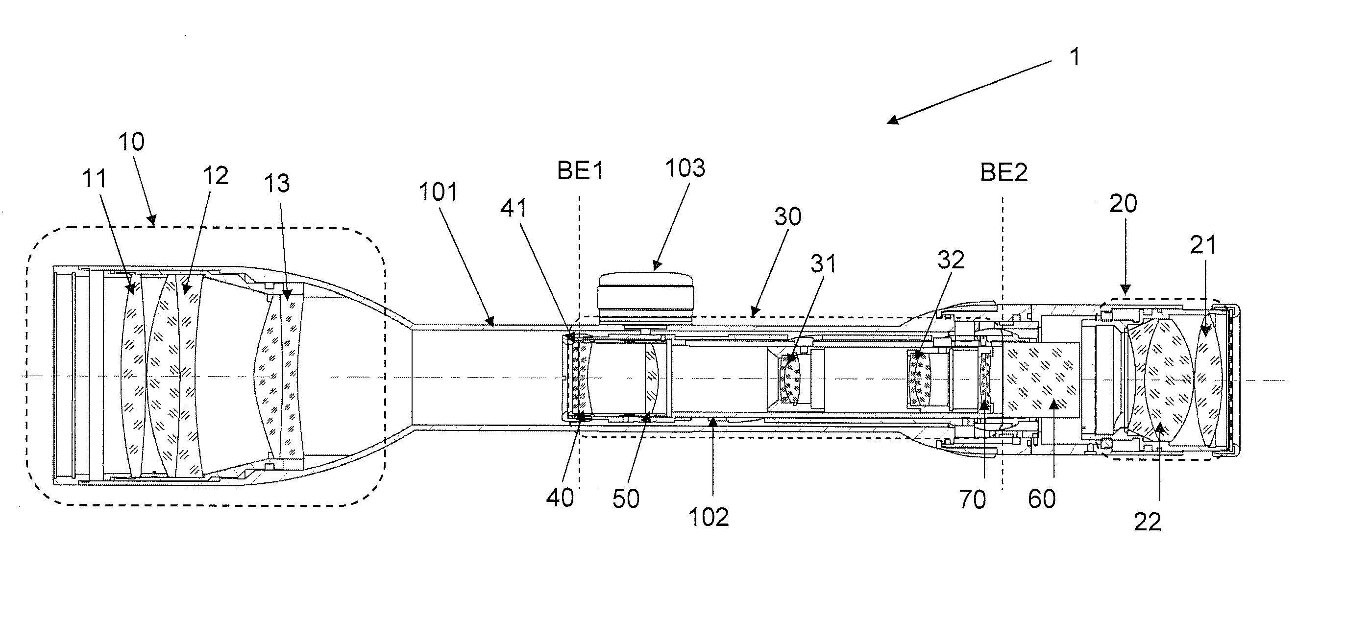
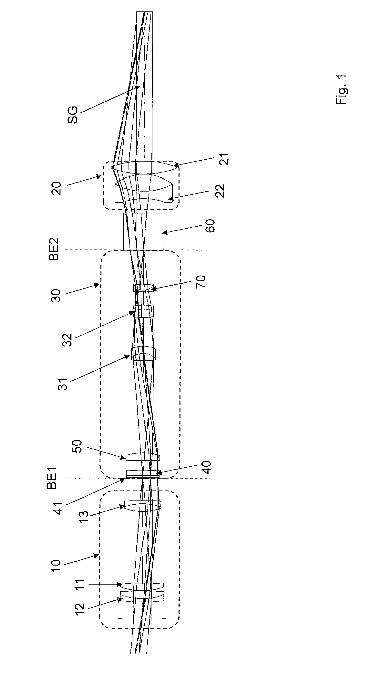
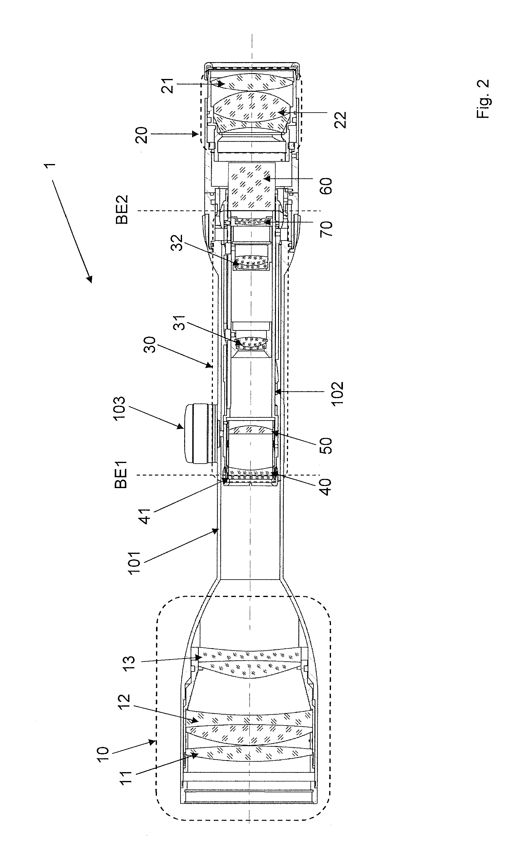
[0050]FIG. 1 shows a cross-section of an optical configuration of the invention and with a beam path SG. A reversing system 30 is configured between an objective 10 and an ocular 20. The reversing system 30 comprises an objective-proximate field lens 50 and two mutually displaceable ocular-proximate optical elements 31, 31, the second optical element 32 being situated closer to the ocular 20 than the first optical element 31. An objective-proximate image plane BE1 is situated between the objective 10 and the field lens 50 and some distance from said field lens. An ocular-proximate image plane BE2 is situated between the ocular 20 and the reversing system 30.

[0051]The objective 10 comprises a first objective achromat 12, an objective lens element 11 configured between the objective achromat 12 and objective-proximate image plane BE1, and a second objective achromat 13 configured between the objective lens element 11 and the objective-proximate image plane BE1. The ocular 20 comprises...


PUM


Abstract

Regarding a sighting telescope comprising a reversing system which is configured between an objective and is fitted an ocular and fitted with an objective-proximate field lens and at least two mutually displaceable optical elements near the ocular, further comprising an objective-proximate image plane situated between the objective and the field lens and spaced from latter, further with an ocular-proximate image plane situated between the reversing system and the ocular, where, when displacing the said optical elements, an intermediate image projected by the objective into the ocular-proximate image plane is erected and reproduced at a variable magnification in the ocular proximate image plane, and at a magnification of at least 4×, the invention stipulates configuring a correcting field lens element between the objective-proximate image plane and the field lens.

Description

FIELD OF THE INVENTION[0001]The present invention relates to a sighting telescope.BACKGROUND ART[0002]Sighting telescopes are used in hunting and for military purposes to aim weapons at targets great distances away. For that purpose these telescopes are fitted with a configuration of lens elements inside a housing to magnify a target view. In particular said configuration includes an objective and an ocular. The objective is a converging optical system to achieve a real target image and the ocular is a system of lens elements allowing the eye to look into said configuration of lenses.[0003]An intermediate image projected from the objective into an objective-proximate image plane is reproduced in an ocular-proximate image plane. However the accompanying magnification substantially restricts the field of view and it is difficult to sight or observe close-by objects. To allow also sighting such objects, the state of the art employs variable magnification, i.e. zooming means. Moreover, ...

Claims


Application Information

Patent Timeline
Patent Type & Authority Patents(United States)
IPC IPC(8): G02B23/02F41G1/38
CPCF41G1/38
Inventor HESSE, HELKE KAREN
Owner SCHMIDT & BENDER
Features
  • R&D
  • Intellectual Property
  • Life Sciences
  • Materials
  • Tech Scout
  • Unparalleled Data Quality
  • Higher Quality Content
  • 60% Fewer Hallucinations
Learn More