Mop with spinning device

a technology of a spinning device and a mops, which is applied in the field of mops, can solve the problems of reducing the life and affecting the operation of the mops, and achieve the effects of reducing noise and vibration, improving shortcomings, and reducing wear

Inactive Publication Date: 2015-02-24
YU TSUNG MOU
View PDF11 Cites 13 Cited by
  • Summary
  • Abstract
  • Description
  • Claims
  • Application Information

AI Technical Summary

Benefits of technology

[0010]A primary objective of the present invention is to provide a mop with a spinning device which has a clutch unit to engage and disengage a driving unit and driven units so as to reduce wear therebetween and prolong the lifetime thereof
[0013]When the unidirectional crown teeth of the sleeve of the clutch unit are engaged with the unidirectional crown gear. The spring between the unidirectional crown gear and the bearing absorbs the impact therebetween so as to reduce wear due to friction, and then reduce noise and vibration.
[0014]The present invention improves the shortcomings of Taiwanese patent application No. 98102868, titled “a mop with a spinning device”, and has a simpler structure and a lower manufacturing cost.

Problems solved by technology

The spiral rod and the unidirectional bearing repeatedly rotate without any buffer arrangement, so that there has a wear problem between the spiral member, the spiral rod and the unidirectional bearing, which affects the operation of the mops and reduces the lifetime thereof.

Method used


Image

  • Mop with spinning device
  • Mop with spinning device
  • Mop with spinning device

Examples


Embodiment Construction

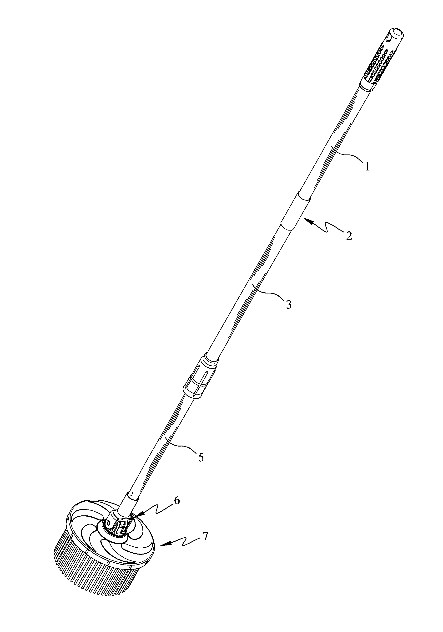
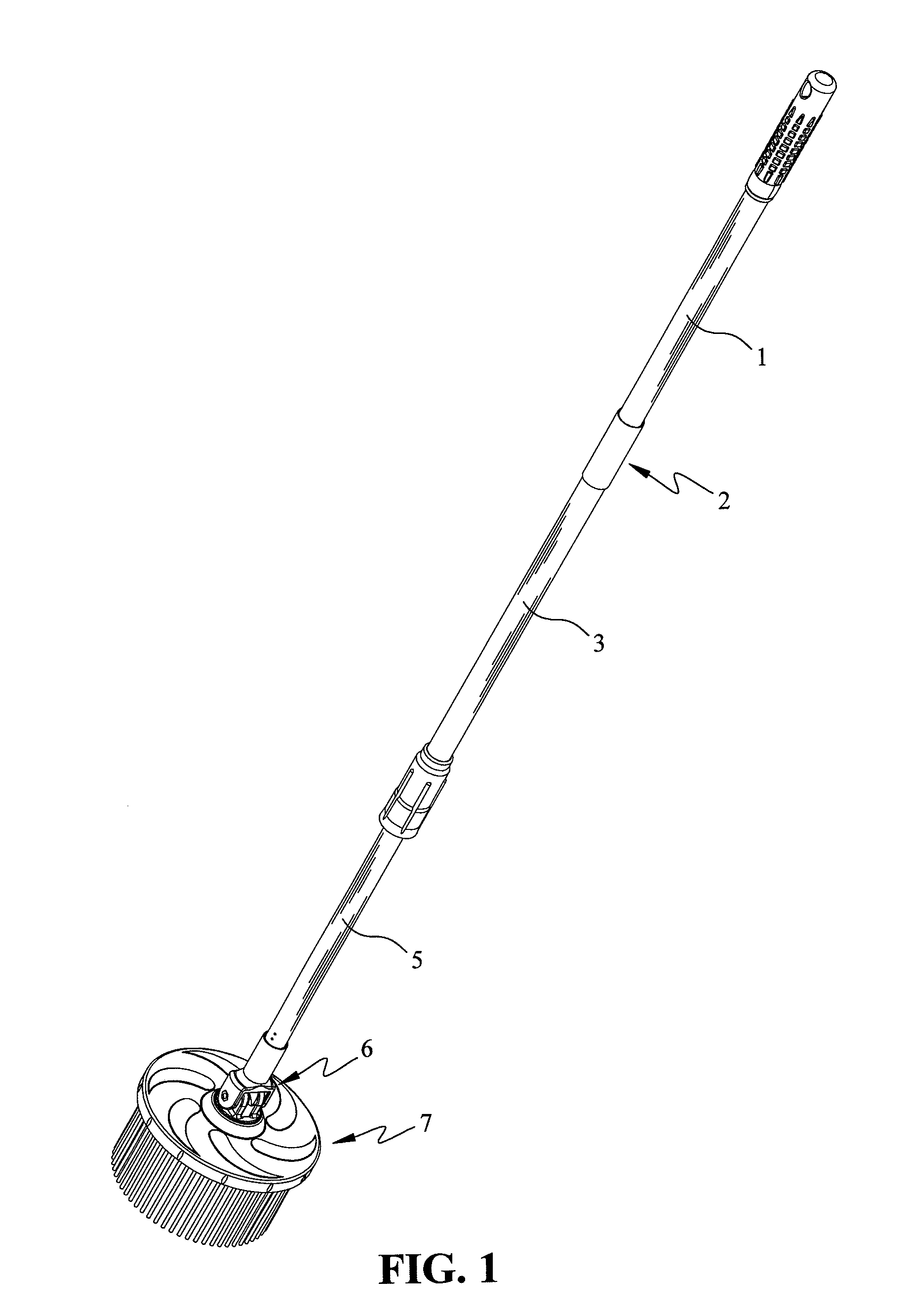
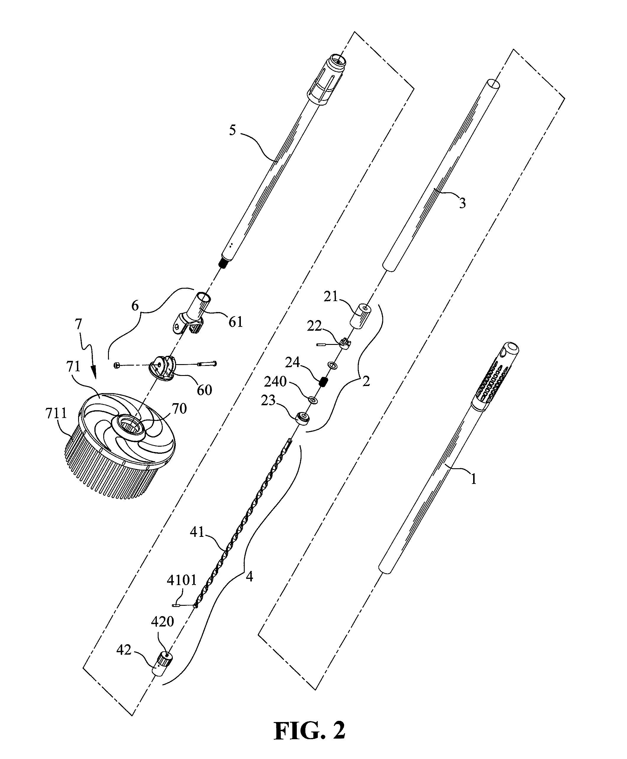
[0023]With reference to the drawings and in particular to FIGS. 1 and 2, a mop in accordance with the present invention comprises a handle 1 connected to a first end of a first rod 3. A second end of the first rod 3 is connected to the second rod 5, which is retractable relative to the first rod 3.

[0024]A driving unit 4 comprises a spiral rod 41 and a spiral member 42 which has a spiral hole 420 defined therethrough. The spiral member 42 is disposed in the second rod 5. The spiral rod 41 inserts through the spiral hole 420 of the spiral member 42, so that the spiral rod 41 can move relative to the spiral hole 420 of the spiral member 42. The spiral rod 41 has a restriction end 410 which has a pin 4101 extending therethrough, so as to stop the spiral member 42 from being disengaged from the spiral rod 41 by the pin 4101.

[0025]Referring to FIGS. 3 to 5, a clutch unit 2 comprises a sleeve 21 disposed in the first rod 3. The sleeve 21 has a unidirectional crown teeth 211 defined in a lo...


PUM


Abstract

A mop includes a handle connected to one end of a first rod. The other end of the first rod is connected to a second rod. A driving unit includes a spiral member disposed in one end of the second rod. A clutch unit is disposed in the first rod. A mopping unit is pivotably connected to the other end of the second rod. The clutch unit includes a sleeve disposed in the first rod and having a crown teeth defined in a lower end thereof. A bearing is connected to an opening of the sleeve, which is rotatable relative to the bearing. A crown gear is disposed in the sleeve and separably engaged with the crown teeth. A spring is disposed between the crown gear and the bearing. The spiral rod inserts through the bearing and the spring and is fixed to the crown gear.

Description

BACKGROUND OF THE INVENTION[0001]1. Field of the Invention[0002]The present invention generally relates to a mop, and more particular to a mop with a spinning device, which includes a clutch unit connected with a driving unit.[0003]2. The Prior Arts[0004]In order to easily remove water from mops, multiple mops with a spinning device are presented in the market; thereby the user can operate the spinning device to let the disk spin to remove the water from the mop.[0005]Among the conventional mops with a spinning device, the mop having a press rod is most popular and comprises a spiral member having a spiral hole defined through the spiral member. A spiral rod inserts through the spiral hole, and a unidirectional bearing is sleeved with the spiral rod. A retractable rod has a first end connected to a mop head, and a second end tightly fitted to a first end of the spiral member. The press rod is sleeved around the spiral rod and has a first end slidably connected to the spiral member a...

Claims


Application Information

Patent Timeline
Patent Type & Authority Patents(United States)
IPC IPC(8): A47L13/20A47L13/14B25G1/04
CPCA47L13/14B25G1/04
Inventor YU, TSUNG-MOU
Owner YU TSUNG MOU
Why Eureka
Try Eureka