Heat transferring engine valve for fuel conservation

a technology of fuel conservation and engine valve, which is applied in the direction of engine starters, machines/engines, muscle operated starters, etc., can solve the problems of specialized cylinders, devices that require mechanically complex regenerators or heat exchangers, and most internal combustion engines operate at far less than maximal efficiency, so as to increase the efficiency of combustion in internal combustion engines

Inactive Publication Date: 2015-02-24
MCGINNIS GEORGE
View PDF2 Cites 6 Cited by
  • Summary
  • Abstract
  • Description
  • Claims
  • Application Information

AI Technical Summary

Benefits of technology

[0006]The present invention provides a heat transferring engine valve reciprocatingly received within the cylinder of an internal combustion engine, including a valve head having a combustion surface directed toward a combustion chamber of the cylinder, and a heat transferring member situated at the combustion surface of the valve head and extending toward the combustion chamber. The heat transferring member absorbs heat from the combustion chamber during the power stroke of an engine cycle and releases the absorbed heat into the combustion chamber during at least the compression stroke of a succeeding engine cycle. The present invention also provides a heat transferring member affixable to the combustion face of a gas exchange valve of an internal combustion engine. The present invention further provides an internal combustion engine cylinder including at least one heat transferring valve. The present invention still further provides a method for increasing the efficiency of combustion in an internal combustion engine, including the steps of providing the valve head of at least one engine valve with a heat transferring member, exposing the heat transferring member to heat of combustion in a combustion chamber during the power stroke of an engine cycle, absorbing heat of combustion into the heat transferring member, releasing heat absorbed heat of combustion from the heat transferring member into the combustion chamber during the succeeding compression stroke of the engine cycle, raising the temperature of the combustion chamber during the compression stroke, and increasing the efficiency of combustion.

Problems solved by technology

Most internal combustion engines operate at far less than maximal efficiency and therefore achieve sub-maximal gas mileage, produce sub-optimal power, and emit high levels of emissions in the form of unburned fuel, carbon monoxide, and oxides of nitrogen.
These prior art devices require mechanically complex regenerators or heat exchangers, or specialized cylinders to carry out particular phases of an engine cycle.
None of these devices can be integrated into, or retrofit onto, standard Otto cycle, Diesel cycle, or other internal combustion engines.

Method used


Image

  • Heat transferring engine valve for fuel conservation
  • Heat transferring engine valve for fuel conservation
  • Heat transferring engine valve for fuel conservation

Examples


Embodiment Construction

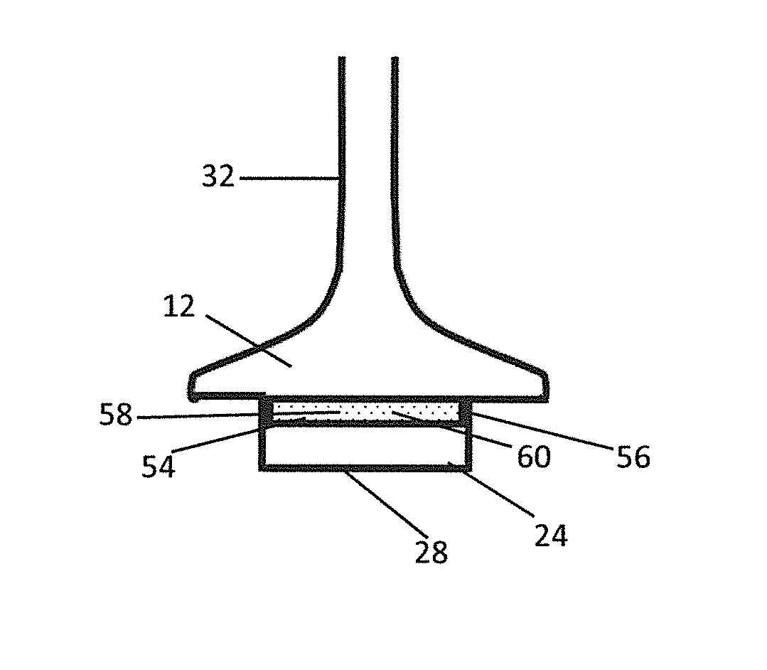
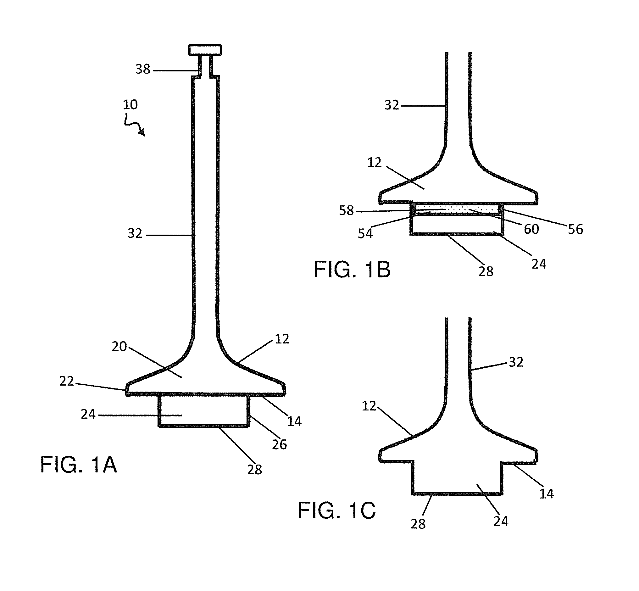
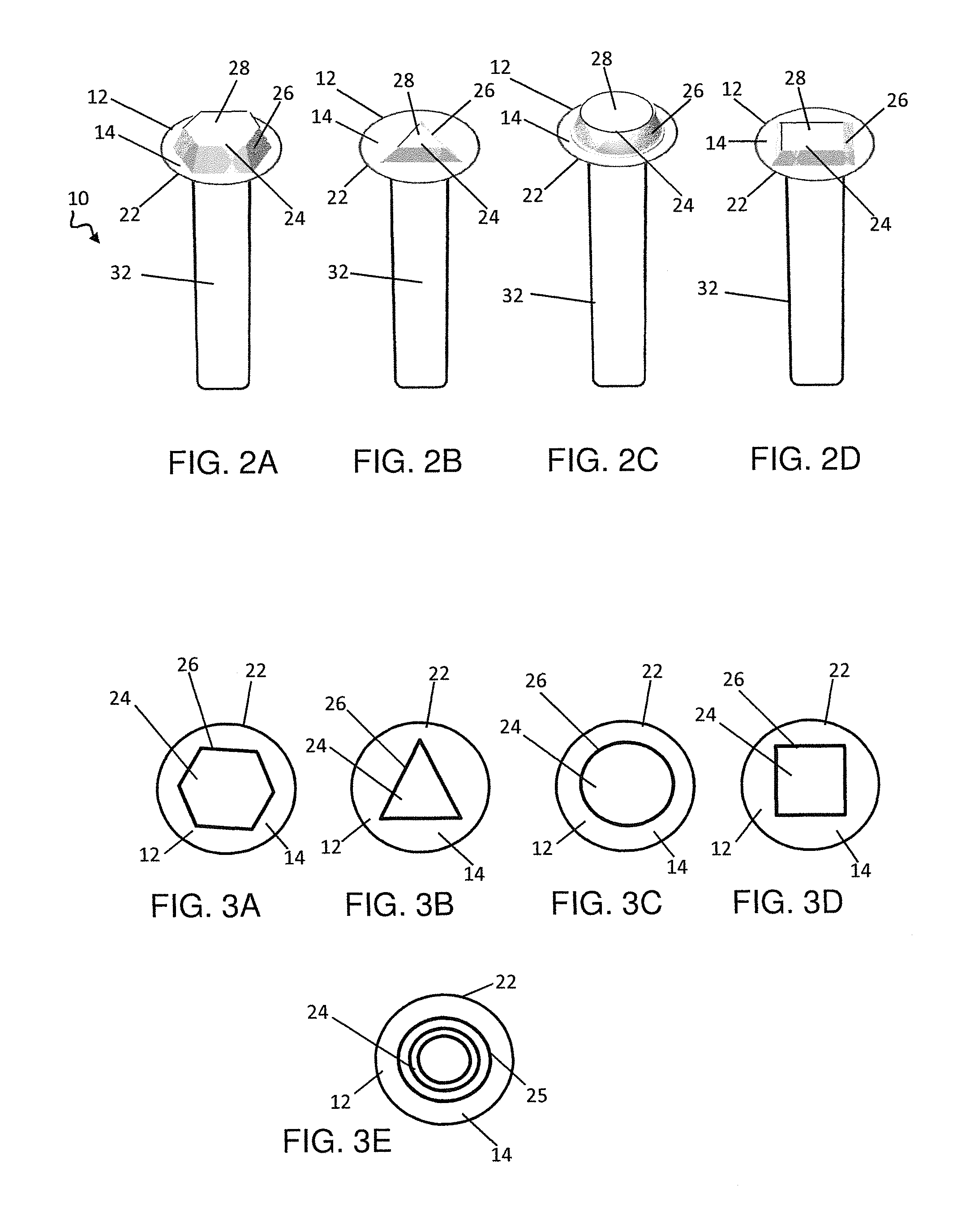
[0025]A heat transferring gas exchange valve according to the present invention, generally shown at 10, includes a generally ovoid or circular valve head 12 including a lower combustion surface 14 directed toward the combustion chamber 16 of a cylinder 18, an opposite upper surface 20, a circumferential margin 22, and a heat transferring member 24 situated at the combustion surface 14 and extending toward the combustion chamber 16. The heat transferring member 24 includes at least one lateral side 26 and a face 28 directed toward the combustion chamber 16.

[0026]In the following description, the term “conventional valve” refers to any engine gas exchange valve that does not include a heat transferring member 26.

[0027]A exemplary heat transferring valve 10, as shown in FIGS. 1A and 6, is preferably a poppet valve reciprocatingly receivable within a valve guide 30 of a cylinder 18. The heat transferring valve 10 also includes support and mounting structures well known in engine valve a...


PUM

PropertyMeasurementUnit
poweraaaaaaaaaa
heat insulatingaaaaaaaaaa
shapeaaaaaaaaaa

Abstract

A heat transferring engine valve for an internal combustion engine to increase the combustion efficiency and fuel economy of the engine. The heat transferring valve includes a valve head and a heat transferring member situated at the combustion surface of the valve head and extending toward the combustion chamber. The heat transferring member absorbs heat of combustion during the power stroke of an engine cycle and releases the heat into the combustion chamber during the compression stroke of a succeeding engine cycle, thereby raising the temperature of fuel at the start of combustion. A method for increasing the efficiency of combustion in an internal combustion engine by incorporating at least one heat transferring valve into the engine.

Description

TECHNICAL FIELD[0001]The present invention relates to the field of internal combustion engines and in particular to the improvement of engine combustion efficiency with fuel-conserving, heat transferring engine valves.BACKGROUND OF THE INVENTION[0002]The gas mileage, power output, and emissions produced by an internal combustion engine depend in large part on the combustion efficiency of the engine, that is, the completeness of oxidation of a hydrocarbon fuel to carbon dioxide, water, and heat. Most internal combustion engines operate at far less than maximal efficiency and therefore achieve sub-maximal gas mileage, produce sub-optimal power, and emit high levels of emissions in the form of unburned fuel, carbon monoxide, and oxides of nitrogen. A well known strategy for increasing the efficiency and mileage of an internal combustion engine is to raise the temperature of the gas mixture present in the combustion chamber during the compression stroke of an engine cycle.[0003]Several ...

Claims


Application Information

Patent Timeline
Patent Type & Authority Patents(United States)
IPC IPC(8): F02N3/00F01L1/34F01L3/00F01L3/02F01L3/20
CPCF01L1/34F01L3/00F01L3/20F01L3/02Y10T29/49231
Inventor MCGINNIS, GEORGE
Owner MCGINNIS GEORGE
Why Eureka
Try Eureka