Bifurcated stent assemblies

a stent and stent technology, applied in the field of stent assemblies, can solve the problems of compromising either the branch vessel or the parent vessel, severe problems of stents, and increased early complications, and achieves the effects of minimal amount of metal bulk, and easy positioning

Active Publication Date: 2015-02-24
INSPIRE M D LTD
View PDF184 Cites 5 Cited by
  • Summary
  • Abstract
  • Description
  • Claims
  • Application Information

AI Technical Summary

Benefits of technology

[0014]In view of the drawbacks of the prior art stent systems for deployment in bifurcated vessels, it would be advantageous to have a bifurcation stent system that is easy to position, creates minimal resistance to flow, and maintains a minimal amount of metal bulk at the entrance to a branch vessel.
[0018]In further embodiments, portions of the stent, and / or stent jacket are coated and / or imbued with active pharmaceutical ingredients (APIs) for the purpose of preventing infection, inflammation, coagulation and / or thrombus formation.
[0108]In embodiments, the mesh comprises fiber having a low diameter that allows each endothelial cell to fully cover and overlap each fiber, thereby forming a layer of endothelial cells that adhere to tissue on either side of the fiber. The thus formed endothelial layer is substantially stable with a substantially reduced tendency to break away and form emboli.
[0109]In embodiments, the mesh fiber comprises material that encourages adherence of endothelial cells, thereby encouraging endothelial layer stability.
[0110]In embodiments, each mesh fiber is spaced a distance from a neighboring fiber thereby preventing a single endothelial cell from adhering to more than one fiber, thereby reducing the chance that endothelial cells will break free of the stent, for example as a result of natural stent pulsation during blood flow.
[0117]In embodiments, the mesh jacket structure comprises a retracted state and a deployed state, and further in the deployed state, the mesh structure defines apertures having a minimum center dimension, which is greater than about 180 micrometers, thus minimizing occurrences of a single endothelial cell adhering to more than one fiber, across one of the apertures, and reducing a chance of endothelial cells breaking free as a result of natural stent pulsation with blood flow.

Problems solved by technology

While mono-tubular stents have resulted in improved long-term blood flow, stents are associated with severe problems when deployed in a bifurcated lumen, meaning a parent lumen from which a branch vessel splits.
Treatment of stenotic lesions at bifurcations is associated with increased early complications including compromise of either the branch vessel or the parent vessel and increased potential for restenosis.
One drawback of this method is the difficulty of properly aligning the side opening of the first stent with the branch vessel bifurcation so that the branch vessel stent passes into the branch vessel.
Another drawback of this system is that the second, flared, stent is difficult to position properly, and may protrude into the blood stream causing thrombosis.
If the first stent is not properly crushed, however, the end of the stent will protrude into the bloodstream, often resulting in thrombosis.
Finally, the crush method deposits a large amount of metal at the entrance to the branch vessel lumen, where the tissue is thin and often incapable of supporting the metallic bulk, resulting in restenosis.

Method used


Image

  • Bifurcated stent assemblies
  • Bifurcated stent assemblies
  • Bifurcated stent assemblies

Examples


Embodiment Construction

[0128]The present invention, which relates to stent assemblies configured for assembling in bifurcating vessels, is herein described, by way of example only, with reference to the accompanying drawings. The principles and operation of the present invention may be better understood with reference to the drawings and accompanying descriptions.

[0129]Before explaining at least one embodiment of the invention in detail, it is to be understood that the invention is not limited in its application to the details of construction and the arrangement of the components set forth in the following description or illustrated in the drawings. The invention is capable of other embodiments or of being practiced or carried out in various ways. Also, it is to be understood that the phraseology and terminology employed herein is for the purpose of description and should not be regarded as limiting.

[0130]Referring now to the drawings:

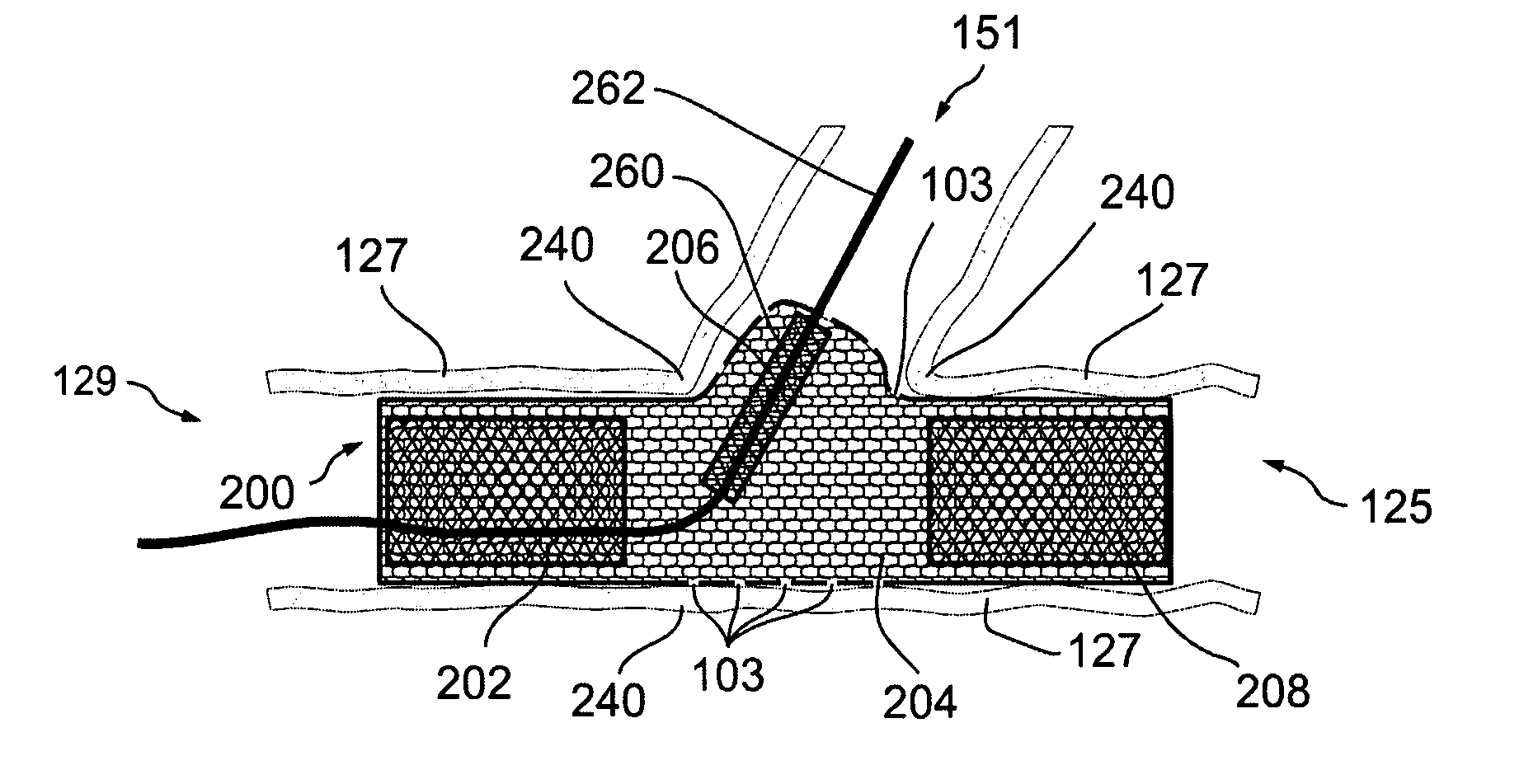
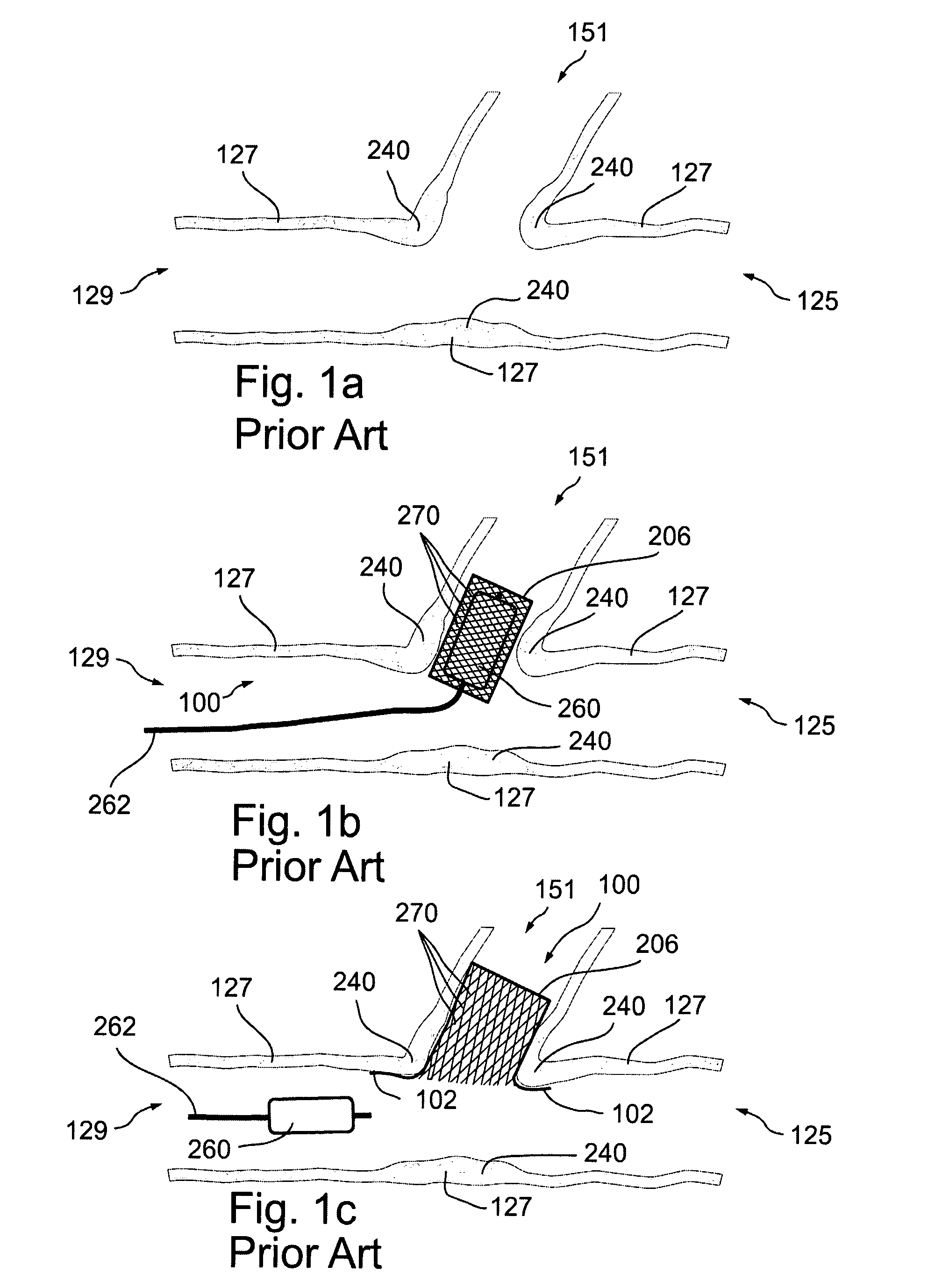
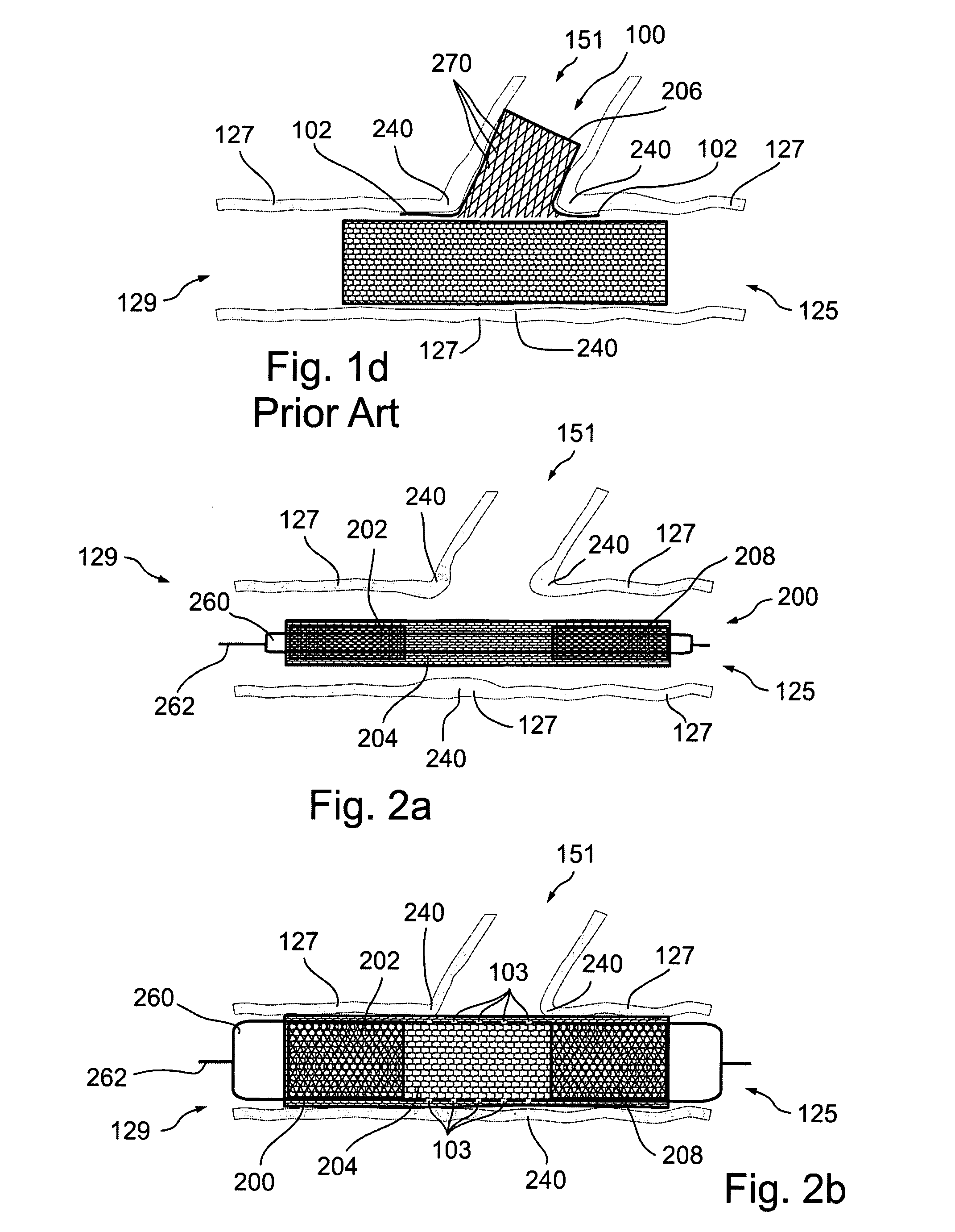
[0131]In FIG. 1a, arteries 127 form an upper branch vessel lumen 151, a...


PUM


Abstract

Disclosed is a stent assembly for expanding in vivo vessels, the assembly comprising first and second radially expandable mesh stents, wherein the first stent is separated by a predetermined distance from the second stent and a stent jacket spans the predetermined distance such that a first end of the jacket is operatively associated with the first stent and a second end of the jacket is operatively associated with the second stent.

Description

RELATIONSHIP TO EXISTING APPLICATIONS[0001]This application is a continuation-in-part of PCT Patent Application No. PCT / IB2006 / 051874 filed May 24, 2006, which in turn claims the benefit of U.S. Provisional Patent Applications Nos. 60 / 683,788 filed May 24, 2005; 60 / 716,100 filed Sep. 12, 2005; and 60 / 742,460 filed Dec. 5, 2005.[0002]This application is also a continuation-in-part of pending U.S. patent application Ser. No. 11 / 582,354 filed Oct. 18, 2006.[0003]In addition, this application claims priority from U.S. Provisional Patent Applications Nos. 60 / 852,392 filed Oct. 18, 2006, 60 / 860,485 filed Nov. 22, 2006, 60 / 860,486 filed Nov. 22, 2006 and 60 / 877,162 filed Dec. 27, 2006.[0004]The contents of the above Applications are hereby incorporated by reference as if fully disclosed herein.FIELD AND BACKGROUND OF THE INVENTION[0005]The present invention relates generally to stent assemblies that are deployed in bifurcated vessels.[0006]While mono-tubular stents have resulted in improve...

Claims


Application Information

Patent Timeline
Patent Type & Authority Patents(United States)
IPC IPC(8): A61F2/82A61F2/954A61F2/852A61F2/856A61F2/90A61F2/958
CPCA61F2/90A61F2/856A61F2/852A61F2/954A61F2/958A61F2002/821A61F2002/826A61F2250/006
Inventor HOLZER, ASHERBAR, ELIPAZ, OFIR
Owner INSPIRE M D LTD
Why Eureka
Try Eureka