Torch tip protector

a torch tip and torch technology, applied in the field of gas torch tip protectors, can solve the problems of insufficient brazing for many steel applications, large bulky types of welders, and hard and stronger steel compositions, and achieve the effects of low cost, easy manufacturing of apparatus, and small siz

Active Publication Date: 2015-02-24
PLUT TRAVIS J
View PDF8 Cites 1 Cited by
  • Summary
  • Abstract
  • Description
  • Claims
  • Application Information

AI Technical Summary

Benefits of technology

[0016]A first object of the invention is to shield and protect torch orifices when not in use. A second object of the invention is to enable the removal of the torch tip protector when the torch is to be used, to ensure that there is no obstruction or interference with torch operation. Another object of the present invention is to accommodate variances in torch tips that might occur either from different manufacturing or from usage. A further object of the invention is to enable one-handed and fluid attachment and removal of the torch tip protector. An additional object of the invention is to provide an apparatus that is suitably heat resistant to not be harmed by likely exposures to hot torch tips and other surroundings. Yet another object of the present invention is to achieve the foregoing objectives with a small, low cost, and easily manufactured apparatus.

Problems solved by technology

However, with the iron age came much harder and stronger steel compositions.
Consequently, brazing is for many steel applications inadequate.
Furthermore, the gases may be stored in relatively small canisters or cylinders, and are readily and, with minimal proper preparation, quite safely and easily transported.
For example, various arc, Metal-Inert-Gas (MIG), Tungsten-Inert-Gas (TIG) and plasma welders have been developed that have great utility, but these types of welders are generally significantly bulkier than an oxyacetylene torch, are less resistant to adverse weather and environment, and they require access to relatively high power electrical sources, some even requiring an industrial three-phase power source.
Since many job sites are not sheltered from the weather or have ready access to high power electrical connection, these newer welding apparatus are limited to use within an adequately wired and sheltered work shop or the like.
This makes the torch extremely oxidizing.
The large flow of oxygen through this larger central jet introduces the excess oxygen to the heated steel, causing the steel to literally burn and release a great deal of additional heat.
While there have been oxyacetylene torches for more than a century, and while these torches are often the tool of choice for remote job sites or for cutting steel, they do suffer from one vexing limitation.
The orifices in the torch tip, particularly the smaller orifices surrounding the central jet but also including the central jet, may be easily clogged with dirt if the torch tip is allowed to drag on the ground.
However, and as already noted herein above, adverse work environments are best suited for this type of torch.
Consequently, all too commonly a welder will unintentionally drag the torch tip, such as when climbing into or out of a depression or hole in the ground or when otherwise transporting the torch.
In such case, the torch may not perform optimally, and the operator may lose significant time either cleaning or replacing a clogged or damaged torch tip.
In spite of the more than one hundred years of use of the oxyacetylene torch, this still today remains an unresolved problem in the field of cutting torches for welders.
Unfortunately, these torch tip devices are open to the torch tip orifices, and so do not prevent debris from clogging the torch tip during transport.
Similar to the Marra and Baker et al patent, these patents are also open to the torch tip, and are installed during torch operation, protecting the torch tip against accidental impact and other useful benefit but failing to protect the torch tip during transport.
While the illustrated cover is undoubtedly of great utility in the single gas torch, there is little teaching for the application to oxyacetylene torches.
However, in using an oxyacetylene cutting torch, the oxyacetylene torch tip is exposed to occasional bits of molten metal or slag that can stick to the torch tip, and the oxyacetylene torch tip, as aforementioned, may be dragged along the ground or the like.
Furthermore, the extremely high temperatures generated by the oxygen and acetylene combustion will heat any outer tubes around the flame nozzle assembly or torch tip, and without the use of very expensive materials will lead to deformation of the metal from repeated heating and cooling.
Consequently, a torch tip cover such as illustrated by Tsai will only have utility in an oxyacetylene torch when the torch tip is new, and will no longer be operative once the cutting torch has been used.

Method used


Image

  • Torch tip protector
  • Torch tip protector
  • Torch tip protector

Examples


Embodiment Construction

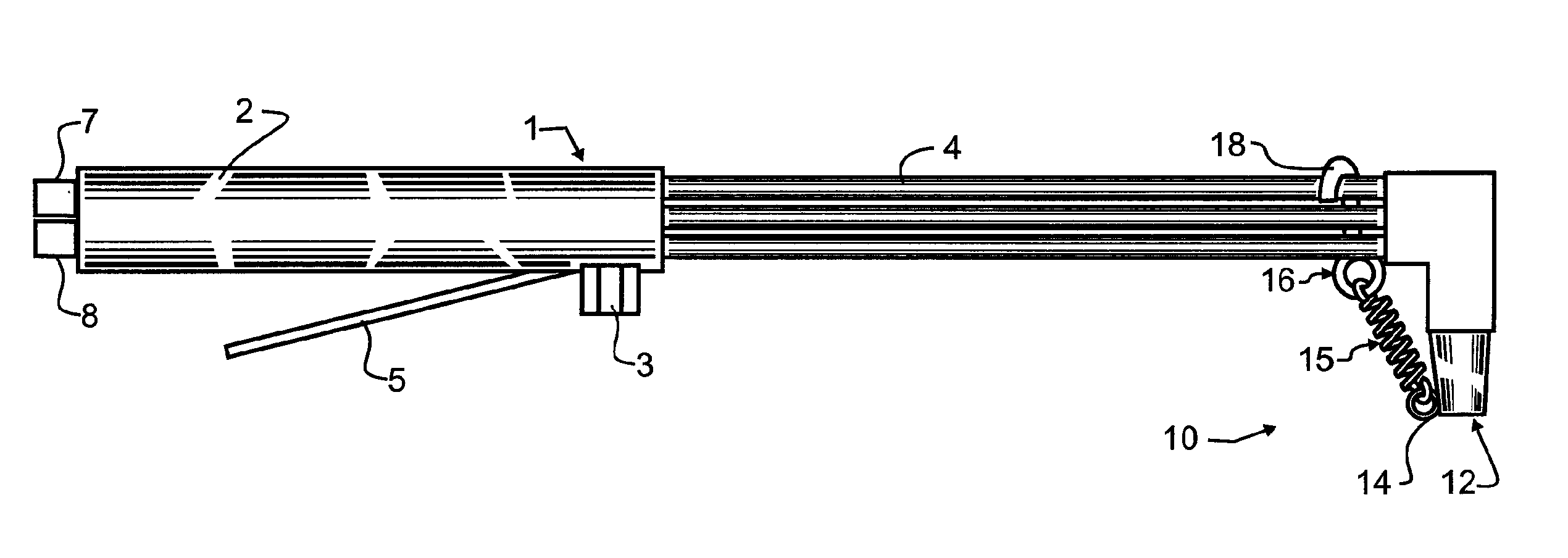
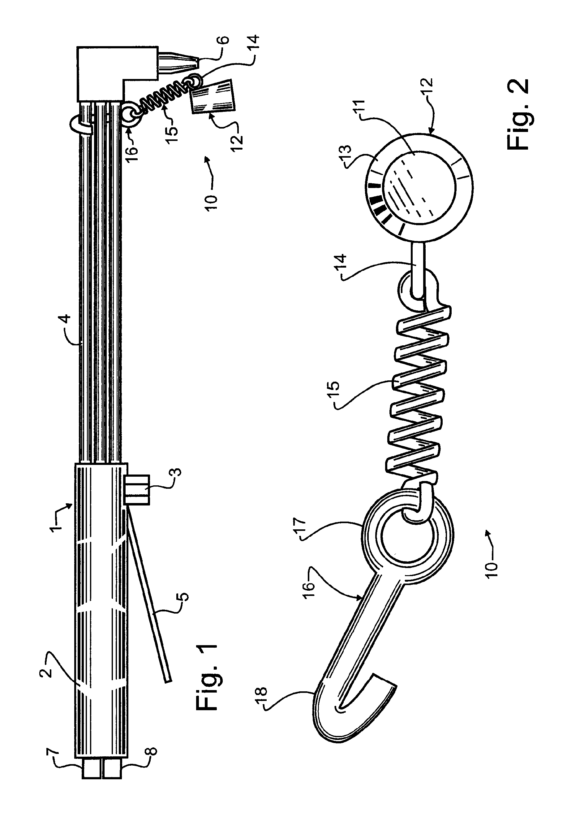
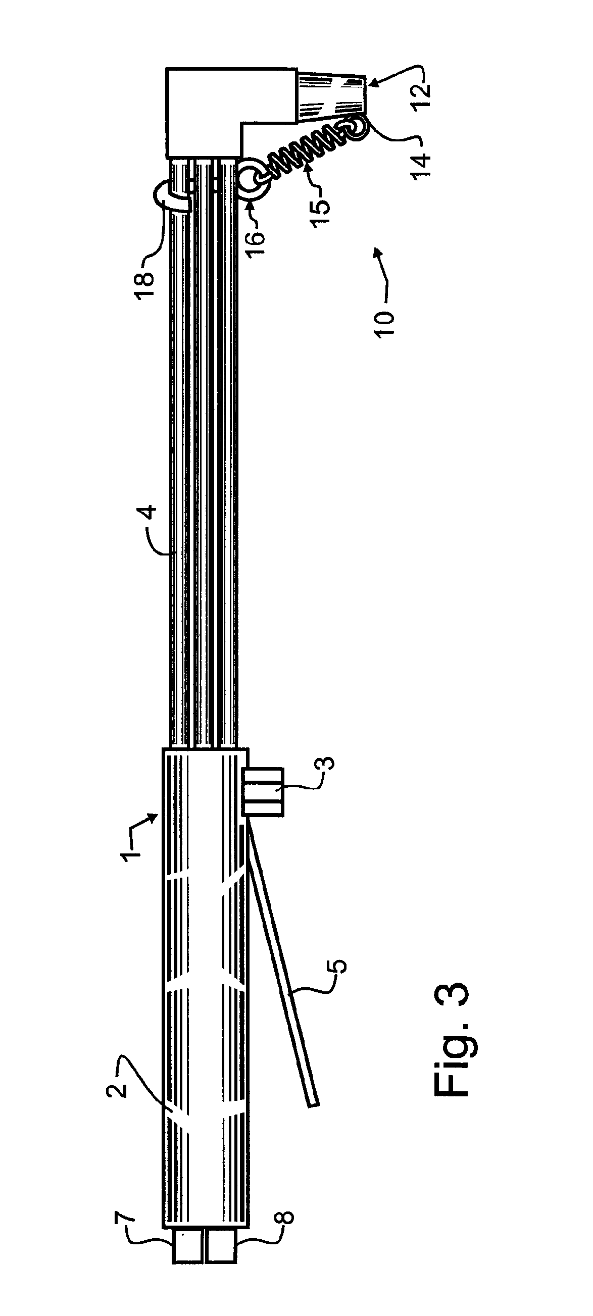
[0021]Manifested in the preferred embodiment, the present invention provides a torch tip protector 10 that is elastically retained to an oxyacetylene cutting torch tip 6. Oxyacetylene cutting torch 1 is coupled to a source of oxygen torch gas 7 as is well-known in the art, and may for exemplary purposes comprise as a hose that couples to a regulator, the regulator in turn coupled through a shut-off valve to an oxygen tank. Oxyacetylene cutting torch 1 is also coupled to a source of acetylene torch gas 8 as is well-known in the art, and may for exemplary purposes comprise as a hose that couples to a regulator, the regulator in turn coupled through a shut-off valve to an acetylene tank. A torch handle 2 may preferably include one or more adjustment valves 3 to permit control of the flow of one or more of the gases directly at torch handle 2. In addition, an oxygen blast trigger 5 will preferably be provided that enables a welder to easily turn on and off a flow of oxygen through a cen...


PUM

PropertyMeasurementUnit
temperaturesaaaaaaaaaa
resistanceaaaaaaaaaa
flexibleaaaaaaaaaa

Abstract

A torch tip protector is elastically retained to an oxyacetylene cutting torch tip during transport. The torch tip protector in the preferred embodiment has a protector cap having a generally disc-shaped base and a truncated conical side wall that together form a cup or thimble-shaped torch tip cover. This torch tip cover operatively encompasses a torch tip and thereby operatively blocks access and fouling of the torch tip. To ensure that the protector cap stays engaged with torch tip, a hook secures to and is manually removable from at least one of the torch gas lines. A spring couples to the hook and couples with the protector cap to provide an elastic tension force that draws the protector cap towards hook and thereby secures the protector cap onto the torch tip.

Description

BACKGROUND OF THE INVENTION[0001]1. Field of the Invention[0002]This invention pertains generally to the field of gas cutting torches such as the well known and widely used oxy-acetylene torches. More particularly, the present invention is a gas torch tip protector that allows the torch to be handled and used in more rugged and extreme environments than was heretofore possible.[0003]2. Description of the Related Art[0004]Nearly from the beginnings of the bronze age, mankind has pursued better ways to work with metal. Metal working has in no small part included ways of bonding together and separating metals. One early bonding technique involved the creation of lower melt alloys that could be used to braze metal together. Brazing and soldering are quite effective for relatively soft and malleable materials such as copper. However, with the iron age came much harder and stronger steel compositions. The strength of a brazed or soldered connection is in most cases far weaker than the int...

Claims


Application Information

Patent Timeline
Patent Type & Authority Patents(United States)
IPC IPC(8): B23K7/00F23D14/38F23D14/46
CPCB23K7/00F23D14/38F23D14/465Y10S266/902
Inventor PLUT, TRAVIS J.
Owner PLUT TRAVIS J
Why Eureka
Try Eureka