Shielding device for an irradiation unit and irradiation method

a shielding device and irradiation unit technology, applied in the direction of radiation therapy, electrode and associated parts arrangement, therapy, etc., can solve the problems of high beam dose, complex and expensive manufacturing of compensator(s) and collimator(s) specific to the tumor of the patient and the irradiation angle, and the weight of such a collimator is relatively large, so as to minimize the penumbra of the beam 2

Inactive Publication Date: 2015-02-24
ION BEAM APPL
View PDF10 Cites 9 Cited by
  • Summary
  • Abstract
  • Description
  • Claims
  • Application Information

AI Technical Summary

Benefits of technology

[0013](ii) providing a block 13 having a longitudinal thickness 6 capable of blocking the passage of said beam 2 and having a lateral surface 7c perpendicular to said longitudinal thickness 6;
[0022]According to a third aspect, the present invention relates to an irradiation unit 14 capable of scanning a hadron beam 2 from a source 3 over a target area 4, said irradiation unit 14 comprising a shielding element 1 according to the second aspect of the present invention, positioned between said source 3 and said target area 4 so as to minimize the penumbra of the beam 2 outside said target area 4.
[0023]According to a fourth aspect, the present invention relates to a method for scanning a target area 4 with a beam of hadrons 2 stemming from a source 3, characterized in that a shielding element 1 according to the second aspect of the present invention is placed in an irradiation unit 14, between said source 3 and said target area 4, so as to minimize the penumbra of said beam 2 outside said target area 4.

Problems solved by technology

A major flaw of this technique is that neighboring tissues localized upstream and outside the target volume may also be subject to high doses from beams.
Further, the manufacturing of the compensator(s) and of the collimator(s) specific to the tumor of the patient and to the irradiation angle is complicated and expensive.
The weight of such a collimator is relatively great, which poses manipulation problems for the therapist.
Often such a collimator is divided into several portions according to its height for facilitating handling, nevertheless the weight of these collimator portions remains great and these portions require accurate alignment relatively to each other.
Because of these two needs, such multileaf collimators have disadvantages in terms of weight and bulkiness of the irradiation unit.
Although the longitudinal thickness along the axes of the beam of such a collimator is reduced because of the high density of the materials used, the application of such a collimator requires the use of relatively costly materials, some of these materials being difficult to machine or being brittle.

Method used


Image

  • Shielding device for an irradiation unit and irradiation method
  • Shielding device for an irradiation unit and irradiation method
  • Shielding device for an irradiation unit and irradiation method

Examples


first embodiment

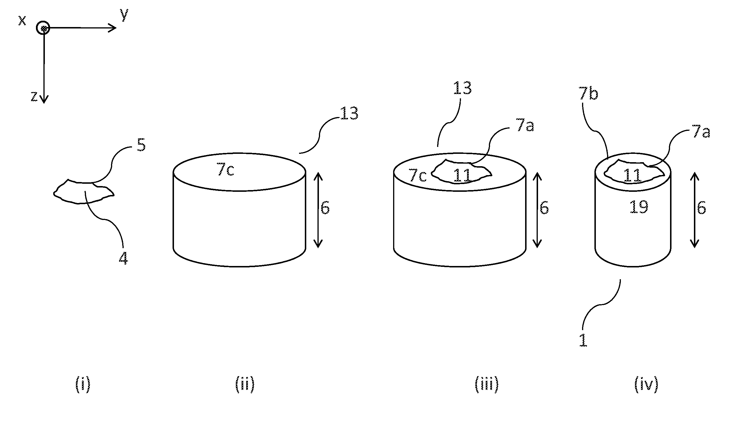
[0041]FIG. 1 illustrates the method according to the present invention in which the contour of the target area defined in step (i) is a closed contour 5.

second embodiment

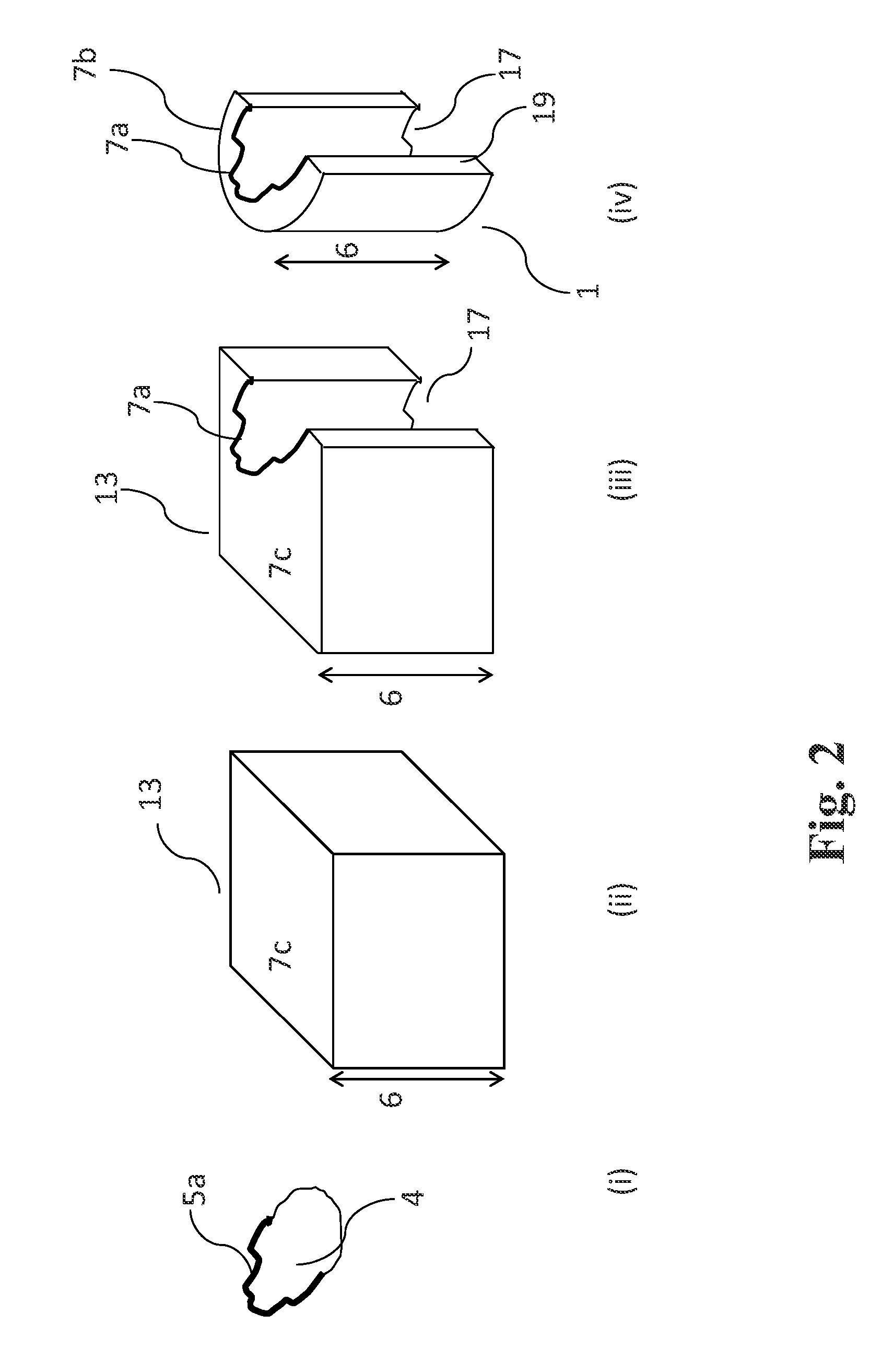
[0042]FIG. 2 represents the method according to the present invention in which the contour of the target area defined in step (i) is an open contour 5a.

third embodiment

[0043]In the method of the present invention, the method for obtaining the shielding element 1 is characterized in that said trimming step (iv) takes into account the width σ of the hadron beam 2 so that said wall 19 has a side thickness everywhere greater than at least once the width σ of said beam. The term of > refers to thickness between the longitudinal internal surface 7a and the longitudinal external surface 7b measured in a direction orthogonal to said axis z and perpendicular relatively to the longitudinal internal surface 7a.

[0044]For a hadron therapy apparatus using a technique for dynamic scanning of a beam over the target area and comprising a beam energy modulator, the width σ of the beam varies depending on the energy of the beam between a minimum value σmin (for example 3 mm) and a maximum value σmax (for example 12 mm). In practice, one skilled in the art may choose to carry out said trimming step (iv) so that the side thickness of the side wall is greater than thr...


PUM

PropertyMeasurementUnit
widthaaaaaaaaaa
weightaaaaaaaaaa
widthaaaaaaaaaa

Abstract

The present invention relates to a method for obtaining a shielding element for minimizing the penumbra of a beam of hadrons outside a target area, the hadron beam being guided in a longitudinal direction by an irradiation unit, and the beam having a width (σ). The method includes:(i) defining a closed or open contour of said target area;(ii) providing a block having a longitudinal thickness capable of blocking the passage of said beam and having a lateral surface perpendicular to said longitudinal thickness;(iii) forming an aperture of a shape similar to said contour and crossing said longitudinal thickness of said block for letting through said beam, said aperture forming a longitudinal internal surface; and(iv) trimming said block so as to form a longitudinal external surface around said longitudinal internals surface, said longitudinal internal and longitudinal external surfaces delimiting a side wall.

Description

CROSS-REFERENCE TO RELATED APPLICATION[0001]This application claims foreign priority under 35 U.S.C. §119 to European Patent Application No. 11169380.0, filed Jun. 9, 2011, which is hereby incorporated herein by reference in its entirety.TECHNICAL FIELD[0002]The present invention according to a first aspect relates to a method for obtaining a shielding element for minimizing the penumbra of a hadron beam outside a target area, said hadron beam stemming from a source and scanning said target area. According to a second aspect, the invention relates to a shielding element made according to the claimed method for obtaining it. According to a third aspect, the present invention relates to an irradiation unit. According to a fourth aspect, the present invention relates to a method for scanning a target area with a hadron beam.DESCRIPTION OF THE STATE OF THE ART[0003]Recent hadron therapy techniques for treating cancers give the possibility of accurately delivering a dose on a target volu...

Claims


Application Information

Patent Timeline
Patent Type & Authority Patents(United States)
IPC IPC(8): G21K1/02A61N5/10G21K1/10
CPCG21K1/10A61N5/1077G21K1/02A61N5/1042A61N2005/1087A61N2005/109A61N2005/1094A61N2005/1095A61N2005/1096Y10T83/0524
Inventor CLAEREBOUDT, YVESCOLMANT, THOMASCLOSSET, MICHEL
Owner ION BEAM APPL
Why Eureka
Try Eureka