Oil immersed stereo wound-core amorphous alloy transformer

a technology of amorphous alloy transformers and wound-core transformers, which is applied in the direction of transformers/react mounting/support/suspension, transformers/inductance magnetic cores, fixed transformers, etc., can solve the problems of high no-load loss of the final assembled iron core, and affecting the performance of the iron core. , to achieve the effect of reducing the impact of external disturbances on the performance of the iron cor

Active Publication Date: 2015-02-24
GUANGDONG HAI HONG
View PDF10 Cites 8 Cited by
  • Summary
  • Abstract
  • Description
  • Claims
  • Application Information

AI Technical Summary

Benefits of technology

[0004]The aim of this invention is to provide an oil immersed stereo wound-core amorphous alloy transformer, which can fully use the advantages of transformers made from amorphous alloy, including, for example, saving energy, reducing production processes, increasing production efficiency, and avoiding the impacts of production on the core performance, as well as saving materials in large degree.
[0011]The present invention provides an oil immersed stereo wound-core amorphous alloy transformer, adopting a stereo-triangle structure comprising three single frames made of amorphous alloy strips by winding. Compared with the existing technologies, the oil immersed stereo wound-core amorphous alloy transformer according to the present invention has the advantages of fewer processing steps, a seamless iron yoke, and less impact of external disturbances on the iron core performance. Fewer processing steps increase production efficiency. The no-load loss of the transformer is further reduced and more energy is saved.

Problems solved by technology

Due to the processes outlined above, the iron core is impacted by usually external forces and subjected to performance degradation.
This leads to higher no-load loss for the finally assembled iron core relative to the bare iron core.

Method used


Image

  • Oil immersed stereo wound-core amorphous alloy transformer
  • Oil immersed stereo wound-core amorphous alloy transformer
  • Oil immersed stereo wound-core amorphous alloy transformer

Examples


Embodiment Construction

[0017]Detailed descriptions of the embodiments of the invention will be made with reference to the drawings.

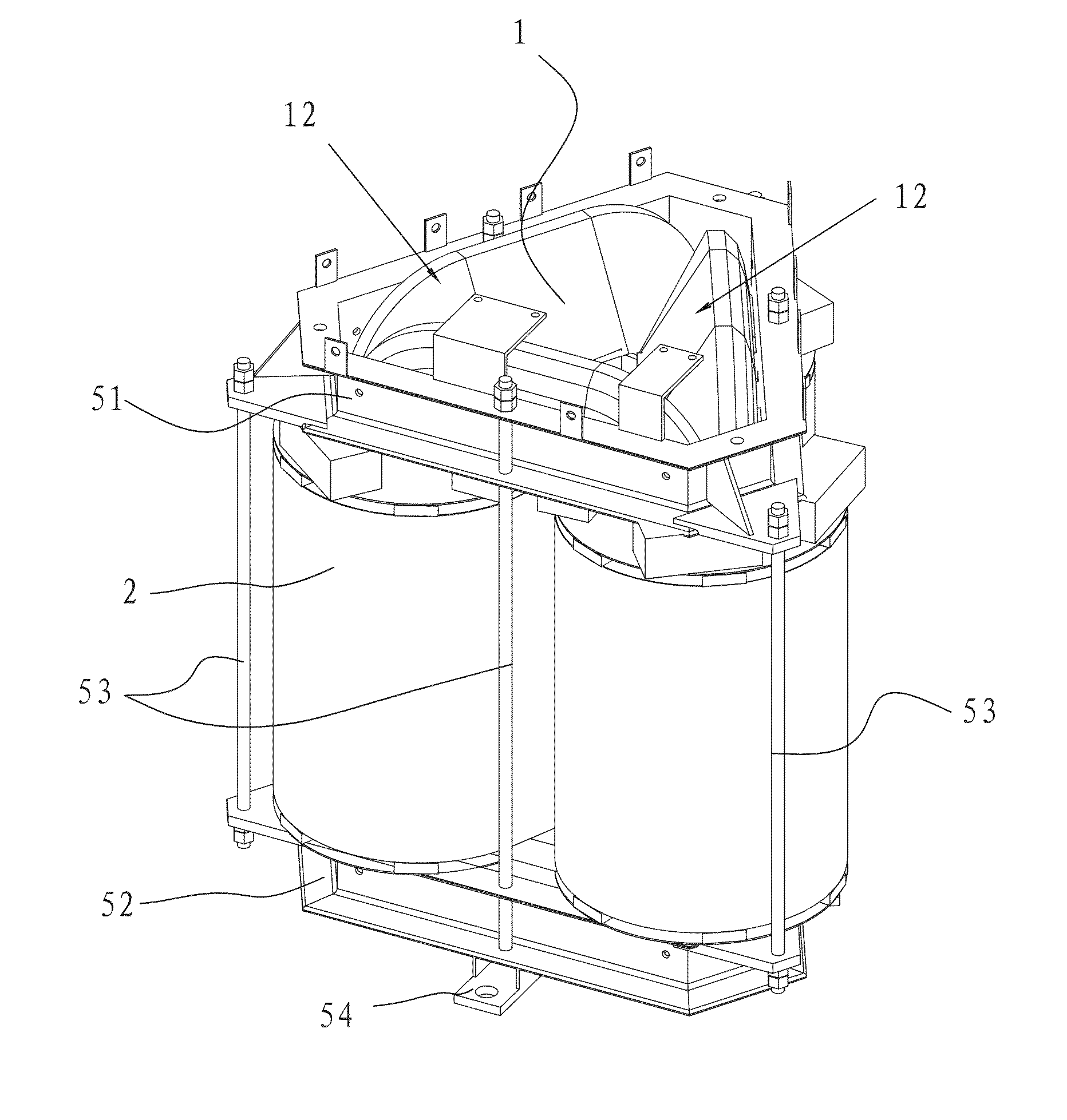
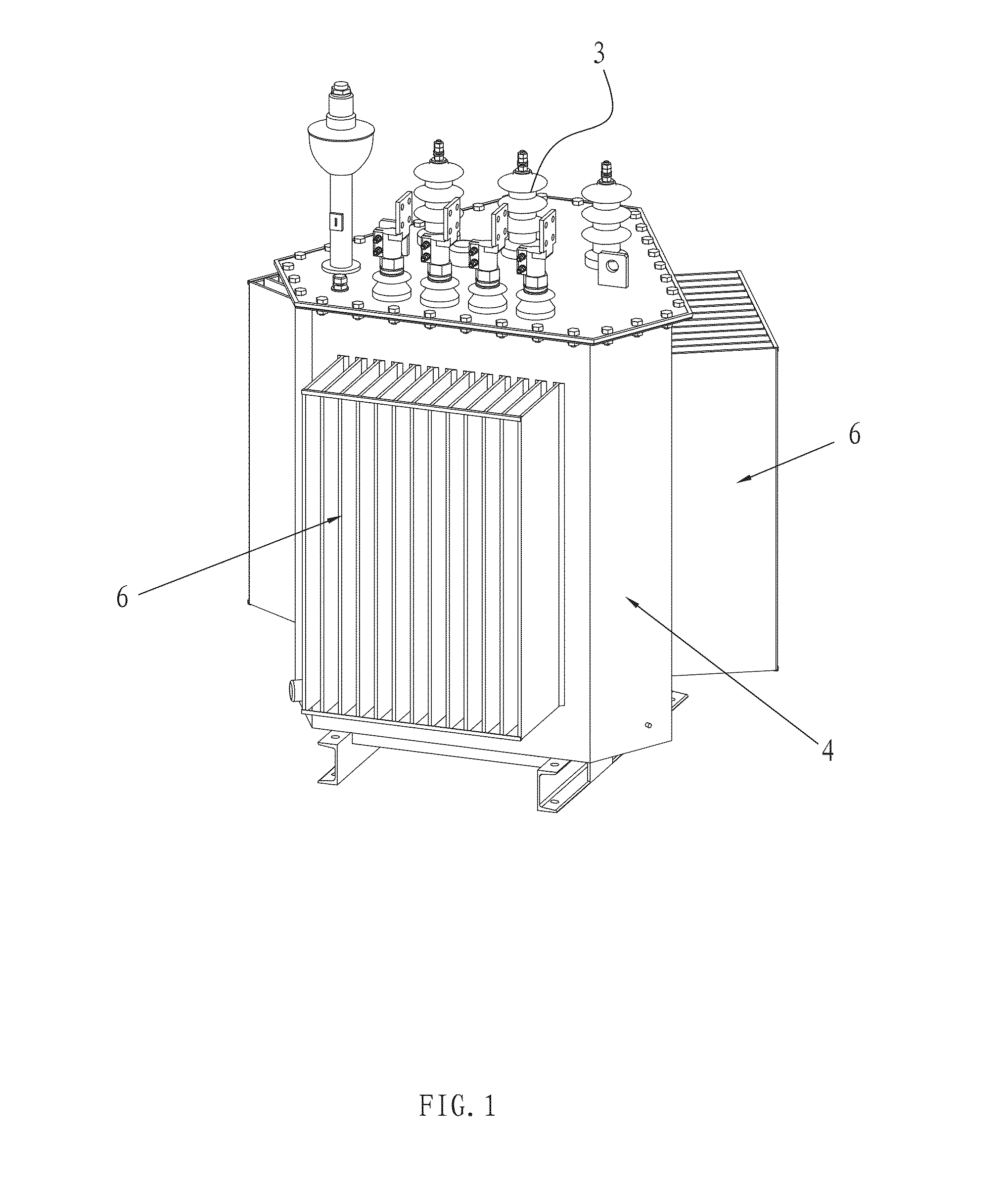
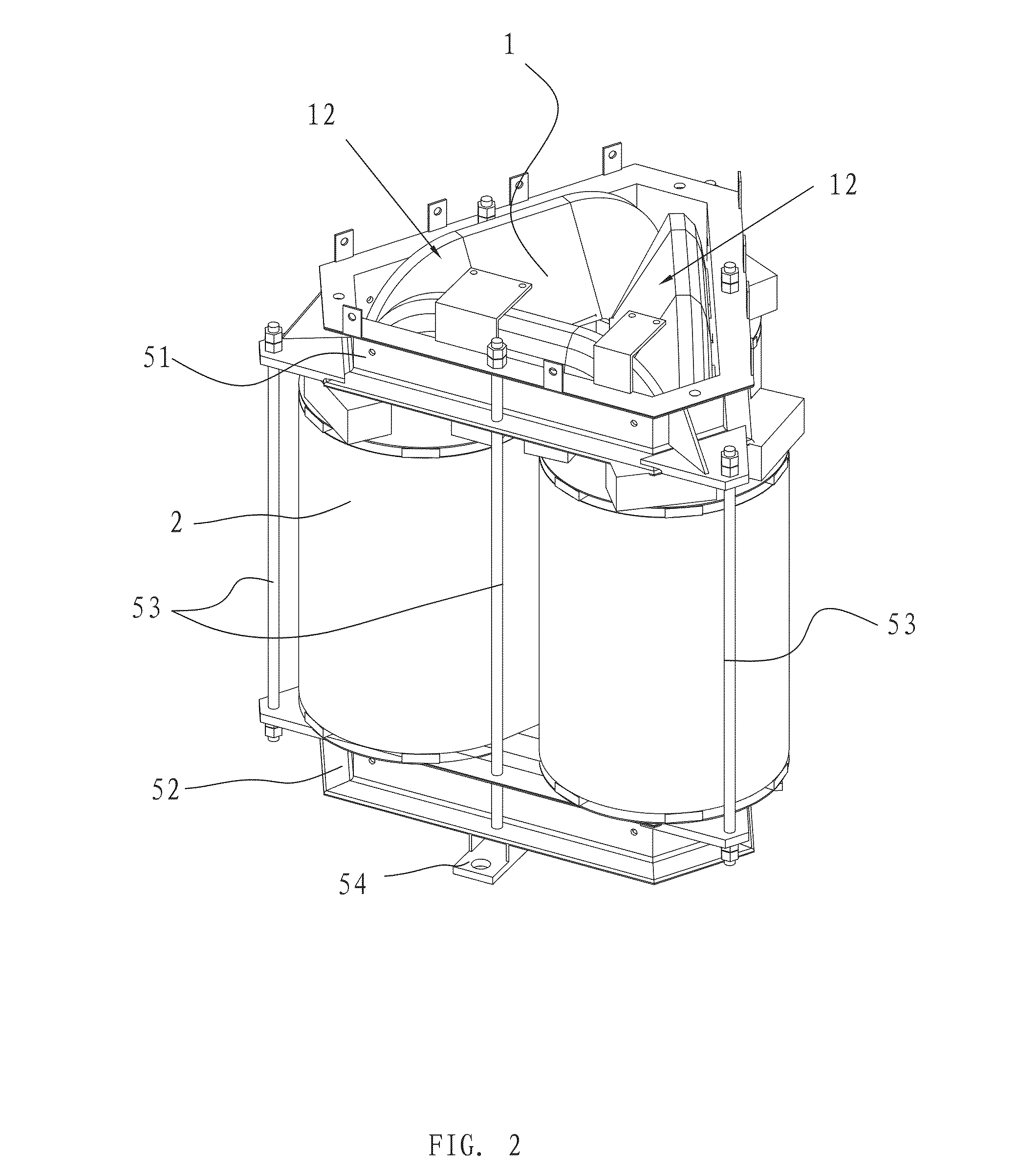
[0018]As shown in FIGS. 1, 2 and 3, the oil immersed stereo wound-core amorphous alloy transformer provided by the present invention comprises an iron core 1, an high-low voltage winding 2, a plurality of leads 3 and a tank 4. As shown in FIG. 4, the iron core 1 has a triangular prism shape. The iron core 1 comprises three rectangular single frames which are made of amorphous alloy strips by winding and are identical in structure. The cross section of the sides of each single frame has a quasi-semi-circular or quasi-semi-polygonal shape. The single frames have semi-circular cross sections with uniform thicknesses. The vertical sides of two adjacent single frames fit together fixedly to form a core pillar 11. The horizontal sides of the single frames form iron yokes 12. Each core pillar 11 is approximately circular or polygonal in cross section.

[0019]As shown in FIG. 3, the tra...


PUM

PropertyMeasurementUnit
thicknessesaaaaaaaaaa
voltageaaaaaaaaaa
external forcesaaaaaaaaaa

Abstract

An oil immersed stereo wound-core amorphous alloy transformer, comprising an iron core, a high-low voltage winding, leads and a tank. The core comprises three single frames made of amorphous alloy strips by winding and are identical in structure, and the single frames have a rectangular shape; the vertical sides of every two adjacent frames fit together fixedly to form a core pillar, and the horizontal sides of the single frame form iron yokes; the cross sections of the core pillars have an approximately circular or polygonal shape; the transformer further comprises a clamp, comprising a quasi-triangular upper and lower clamp, and posts, the lower clamp is provide with three food pads; the iron yokes in the lower portion of the iron core are located on the foot pads, and the high-low voltage winding is wound on the core pillars.

Description

TECHNICAL FIELD[0001]This invention is in the field of power equipment, and particularly relates to an oil immersed amorphous alloy transformer with stereo structure.BACKGROUND[0002]For conventional oil immersed amorphous alloy transformers, the iron cores and windings are manufactured separately, and subsequently the wound windings are sleeved onto the core pillars in assembly. During production, an iron core is processed through a series of steps, including iron yoke seam opening, winding sleeving, seam closing, winding pressing, and so on. Due to the processes outlined above, the iron core is impacted by usually external forces and subjected to performance degradation. This leads to higher no-load loss for the finally assembled iron core relative to the bare iron core.[0003]In addition, a conventional amorphous alloy iron core is usually of a three-leg or four-frame five-leg structure, wherein the three-phase windings are arranged in one line. Its tank is of a rectangular structu...

Claims


Application Information

Patent Timeline
Patent Type & Authority Patents(United States)
IPC IPC(8): H01F27/26H01F30/12H01F27/10H01F27/24H01F27/02H01F27/00H01F27/06H01F27/25H01F27/30
CPCH01F27/06H01F27/008H01F27/26H01F27/306H01F30/12H01F27/25H01F27/24H01F27/30
Inventor XU, KAIXUANGUO, XIANQING
Owner GUANGDONG HAI HONG
Why Eureka
Try Eureka