
Liquid crystal display panel and gate driver circuit of a liquid crystal display panel including shift registers

a technology of shift registers and which is applied in the field of gate driver circuits of liquid crystal display panels, can solve the problems of increasing the difficulty of designing, the headache of designers, and the increase of delay of signals, so as to reduce the board area occupied by the gate driver circuit, the gate driver circuit is substantially simplified, and the rc distortion of inputted frequency signals (clock signals) is reduced

Inactive Publication Date: 2015-02-24
TCL CHINA STAR OPTOELECTRONICS TECH CO LTD
View PDF3 Cites 4 Cited by
  • Summary
  • Abstract
  • Description
  • Claims
  • Application Information

AI Technical Summary

Benefits of technology

[0010]The present invention only requires ((N / 2)+1)th shift registers for outputting N gate signals to the N gate lines. Therefore, the gate driver circuit is substantially simplified, the RC distortion of inputted frequency signals (clock signals) is reduced, the board area occupied by the gate driver circuit is reduced, and the dependability of the gate driver circuit is enhanced.

Problems solved by technology

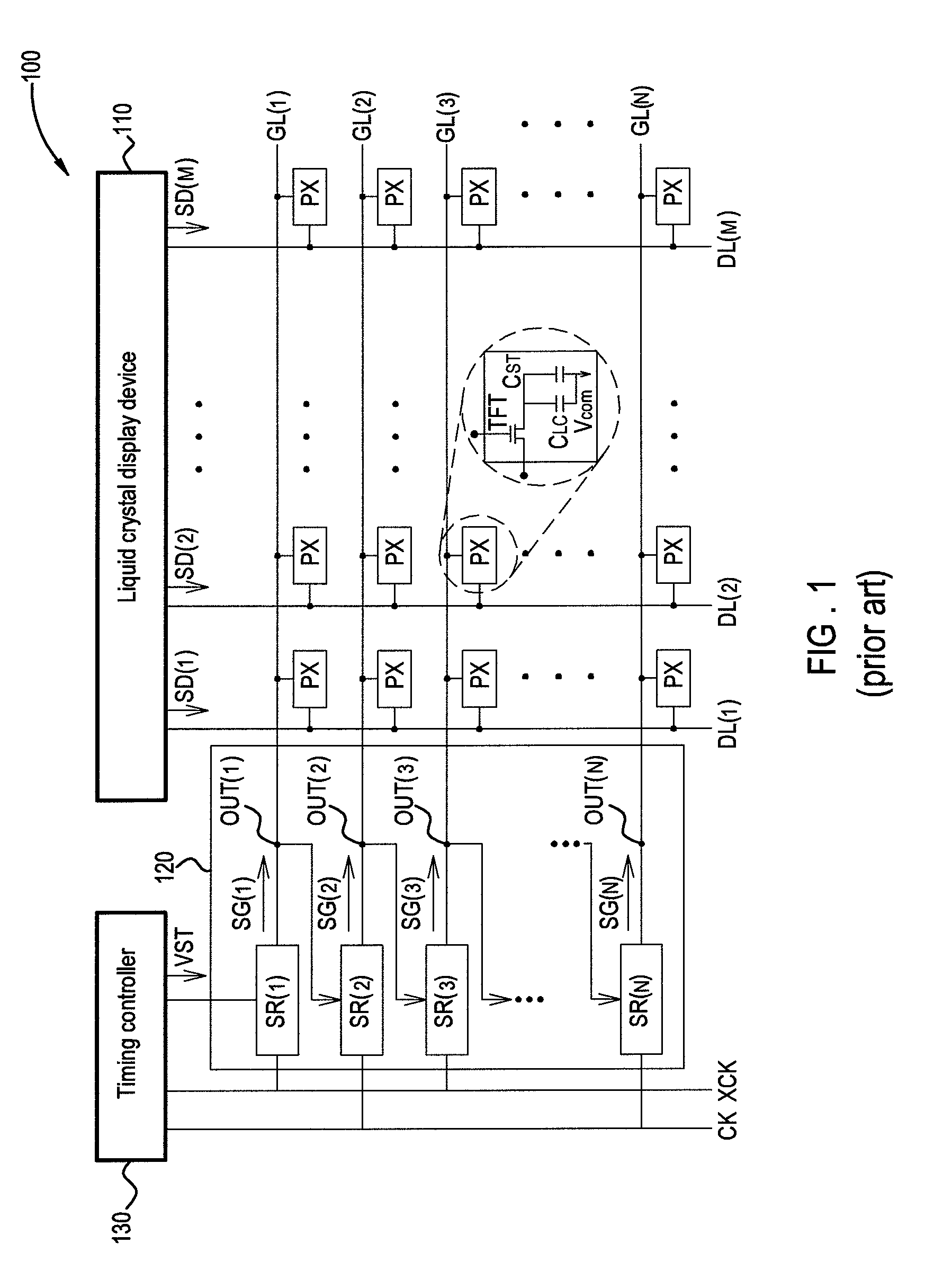
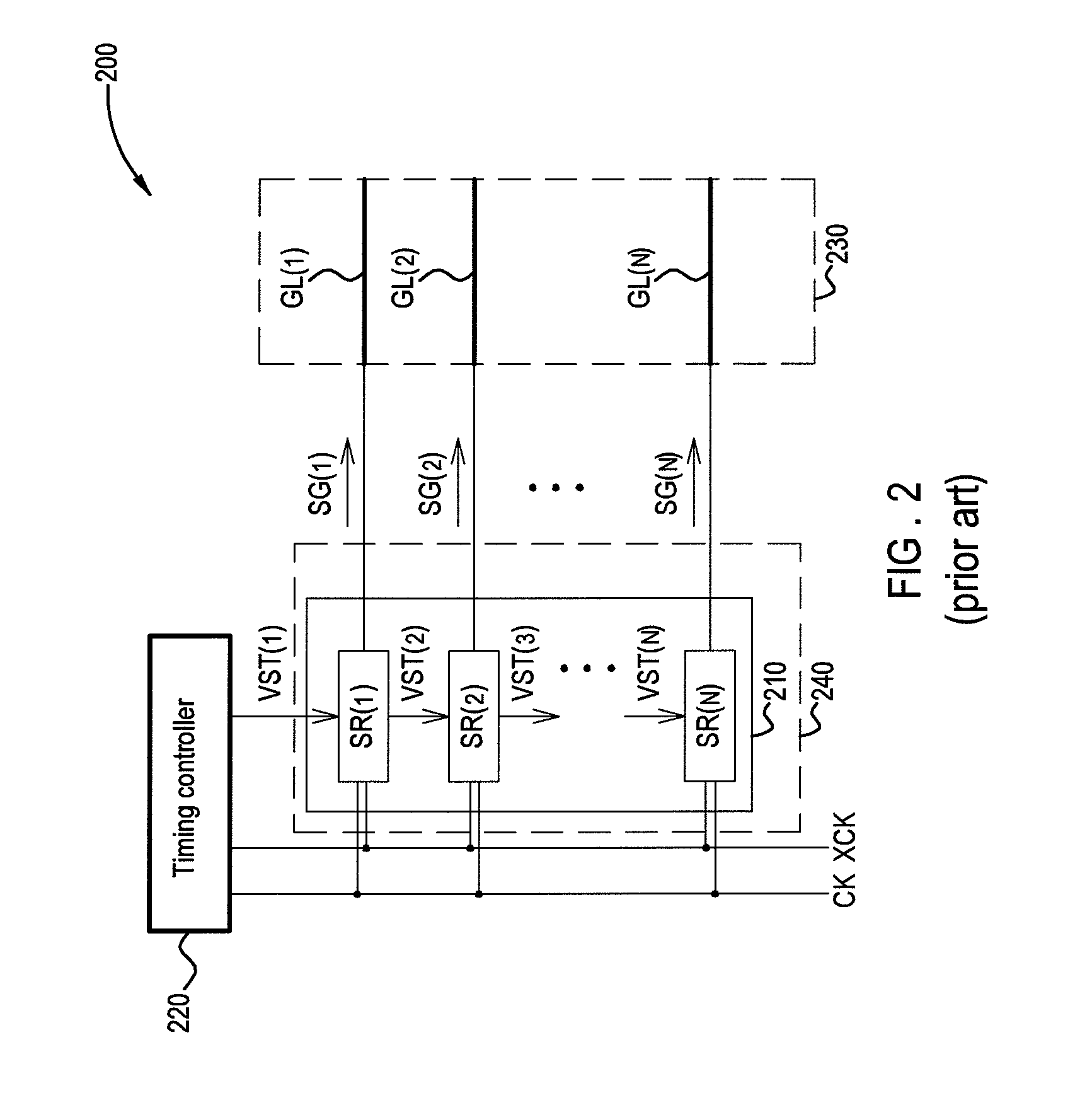
It is well known that the technology of gate on array (GOA) or gate in panel (GIP) for integrating gate driver circuits on a liquid crystal display device (TFT-LCD) panel can reduce the costs of integrated circuits, and the size of a board area around the panel; however, problems related to dependability, stability and power consumption of the complicated GOA circuits on the panel are headaches for designers.
External signal lines are also required to enter into more than N shift registers at the same time, thus problems with high power consumption and delay of signals will get more serious.

Method used


Image

  • Liquid crystal display panel and gate driver circuit of a liquid crystal display panel including shift registers
  • Liquid crystal display panel and gate driver circuit of a liquid crystal display panel including shift registers
  • Liquid crystal display panel and gate driver circuit of a liquid crystal display panel including shift registers

Examples


Embodiment Construction

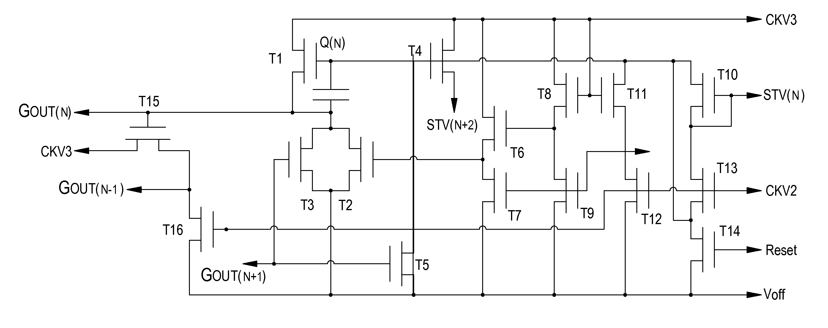
[0025]Referring to FIG. 4, it shows a first embodiment of a liquid crystal display panel 310 of the present invention. The liquid crystal display panel 310 comprises N gate lines (scan lines) GL(1) to GL(N) and M data lines DL(1) to DL(M). The gate lines GL(1) to GL(N) and the data lines DL(1) to DL(M) define N×M pixels, N and M are even numbers bigger than two. The gate lines GL(1) to GL(N) are electrically connected to a gate driver circuit 312, and the data lines DL(1) to DL(M) are electrically connected to a source drive circuit 314.

[0026]The liquid crystal display panel 310 comprises a plurality of pixel units arranged in an array, and each of the pixel units at least includes a gate line, a data line, a thin film transistor (TFT), a liquid crystal capacitor and a storage capacitor. The TFTs are acted as switches for the pixel units, while the gate lines and the data lines provide appropriate operational voltages for the selected pixel units, in order to have each of the pixel ...


PUM


Abstract

A liquid crystal display panel comprises N gate lines, wherein N is an even number bigger two, and a first gate driver circuit which includes ((N / 2)+1)th first shift registers connected in series, for outputting N gate signals to the N gate lines. The present disclosure only requires ((N / 2)+1)th shift registers for outputting N gate signals to the N gate lines. Therefore, the gate driver circuit is substantially simplified, the RC distortion of inputted frequency signals (clock signals) is reduced, a board area occupied by the gate driver circuit is reduced, and the dependability of the gate driver circuit is enhanced.

Description

FIELD OF THE INVENTION[0001]The present invention relates to a liquid crystal display panel, and more particularly to a gate driver circuit of a liquid crystal display panel.BACKGROUND OF THE INVENTION[0002]Liquid crystal displays (LCD) which have advantages of low radiation, compact in size and low energy consumption, are gradually replacing conventional cathode ray tube displays, therefore they are widely used in electronic products such as laptops, personal digital assistants (PDA), flat panel televisions or mobile phones, etc. Conventional liquid crystal displays employ external driver chips to drive the pixels on the panels to display images or pictures. In order to decrease the number of components used and to reduce manufacturing costs, in the recent years, it is gradually developed to have the structures of drive circuits integrated directly on the display panels; for example, the gate on array (GOA) technology is applied to integrate gate driver circuits on a liquid crystal...

Claims


Application Information

Patent Timeline
Patent Type & Authority Patents(United States)
IPC IPC(8): G09G3/36
CPCG09G3/36G09G3/3677G09G2310/0281G09G2310/0286G09G2320/0223G09G2330/021G11C19/28
Inventor ZHOU, XIU-FENGXU, ZHENG-XING
Owner TCL CHINA STAR OPTOELECTRONICS TECH CO LTD
Learn More