Thermo-kinetic compressor

a compressor and thermokinetic technology, applied in the direction of mixing methods, fuel gas production, and using liquid separation agents, can solve the problems of low energy efficiency, low energy efficiency, and compression is far from adiabatic, and achieve the effect of reducing pressure and high speed

Inactive Publication Date: 2005-08-30
HAIUN JOSEPH
View PDF14 Cites 49 Cited by
  • Summary
  • Abstract
  • Description
  • Claims
  • Application Information

AI Technical Summary

Benefits of technology

[0013]The device according to the invention, which uses neither mechanical energy nor kinetic entraining energy but only thermal energy to compress the gas, enables most of these disadvantages to be overcome through the use of a different cycle, consisting in pre-processing the gas for compression and in giving it thermal energy directly, in reducing its pressure at sonic or supersonic speed through pressure reduction nozzles, in removing heat at high-speed and thus at low temperature by spraying and controlled evaporation of liquid distributed in a pressure reduction-cooling nozzle, with the nozzle enabling a high speed to be maintained, and finally in recompressing this gas in an adiabatic compression nozzle in order to reduce its speed to a normal outflow value; the pressure reduction nozzles, the pressure reduction and cooling nozzles, and the adiabatic compression nozzles can be fitted with a variable geometry system, enabling the sections of their inlet and / or outlet necks to be adjusted to regulate, among other things, the device's flow and compression rates.

Problems solved by technology

Compressors in the current state of the technology require substantial maintenance due to the mechanical friction and the wear and tear which result, and have low energy efficiency levels, or even very low ones in the case of ejectors, due essentially:
To the reheating of the gas for compression when it is compressed, which inevitably means that the compression is far from being adiabatic,
To deposits and soilings on the air compressors: even frequent washings of the gas turbine compressors can only attenuate the effect of these soilings.

Method used


Image

  • Thermo-kinetic compressor
  • Thermo-kinetic compressor
  • Thermo-kinetic compressor

Examples


Embodiment Construction

Basic Version 1

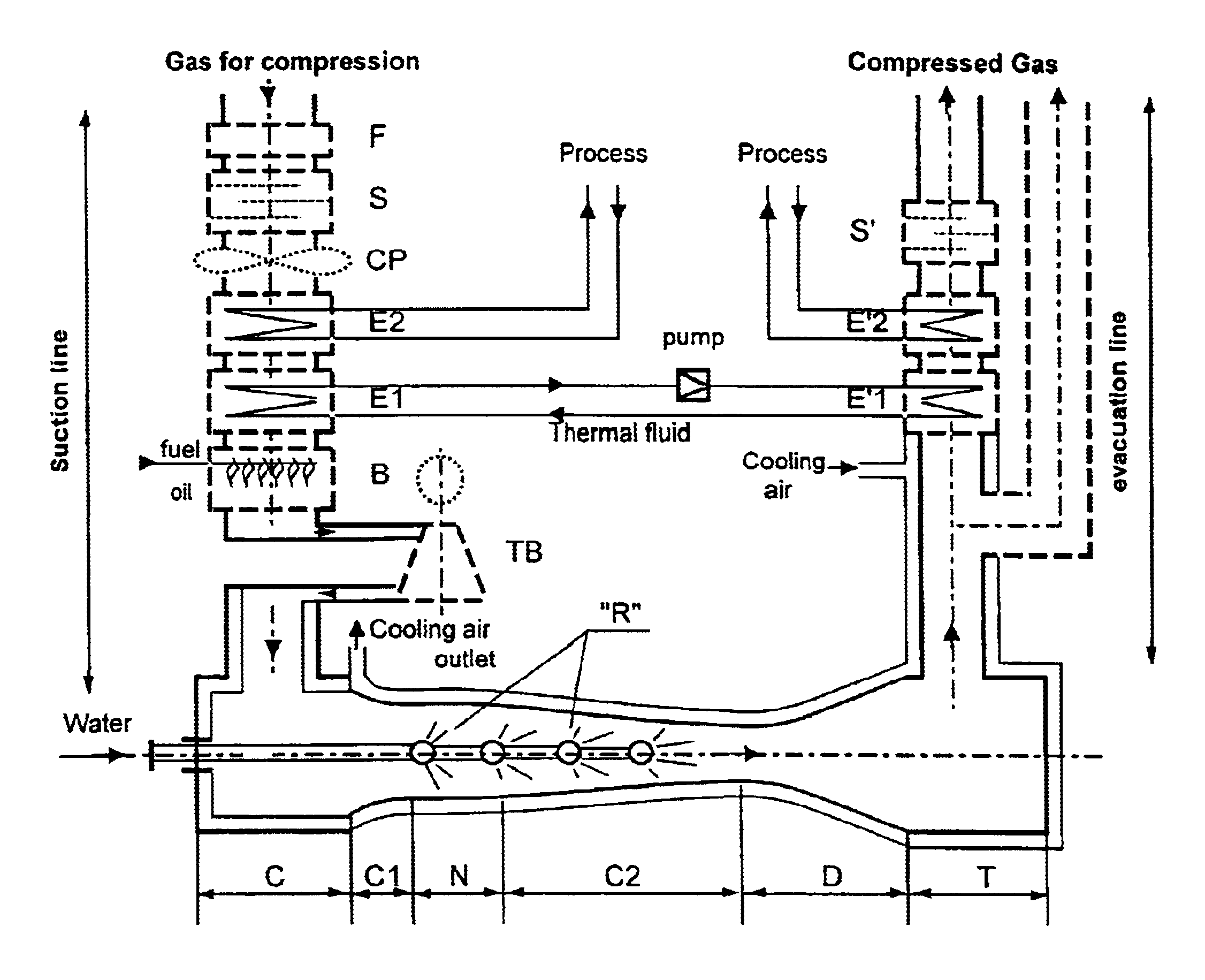
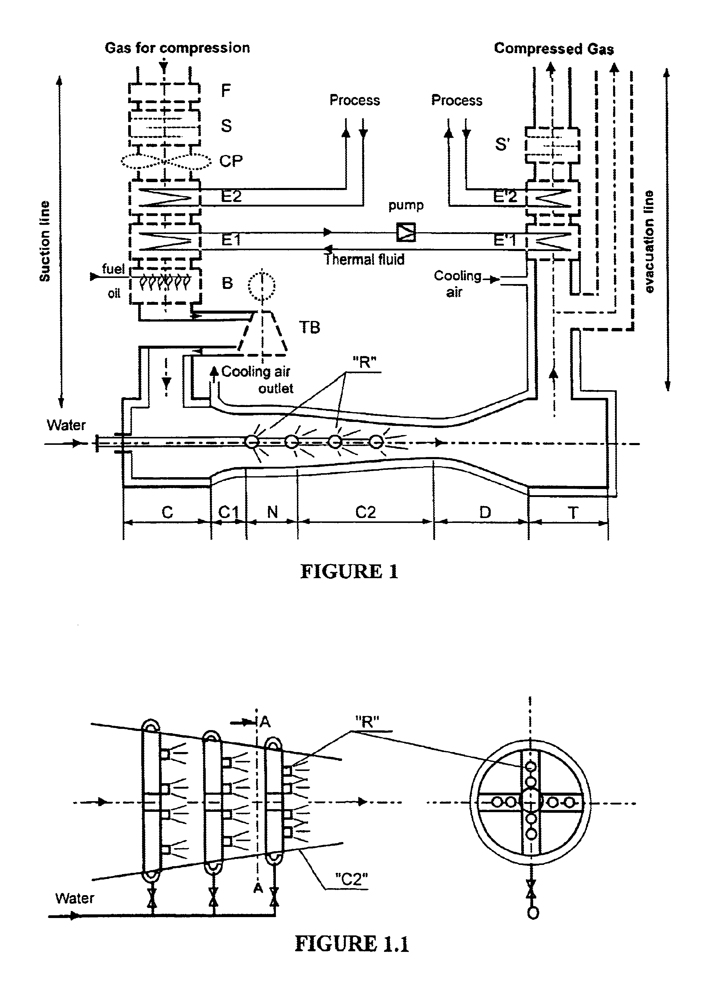
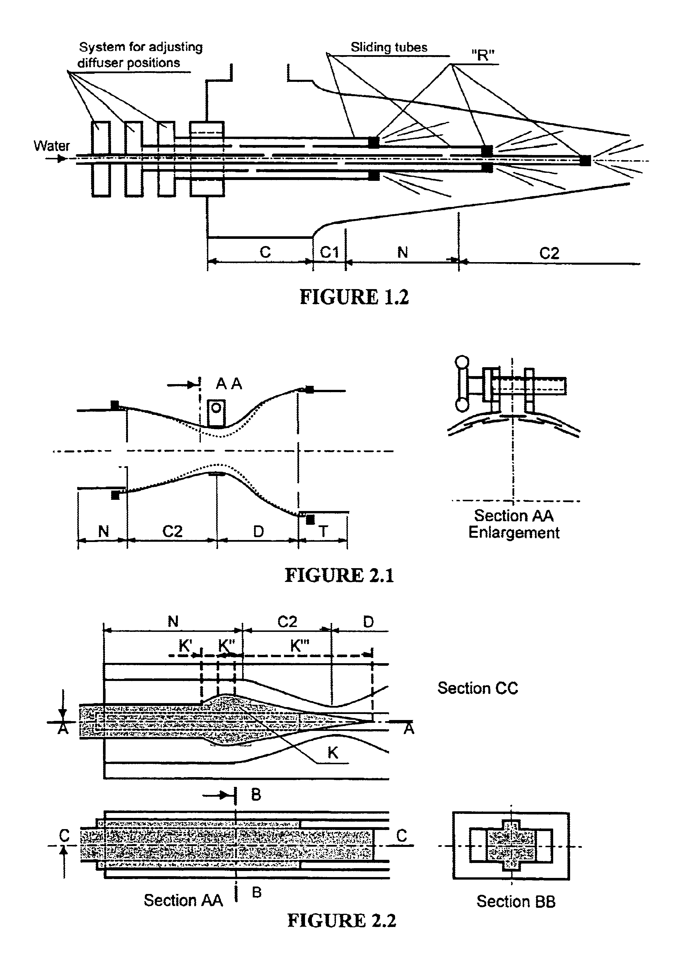
[0043]It its simplest concept, which we shall call Basic Version 1, represented by FIG. 1, the device according to the invention uses a subsonic or sonic outflow; it contains a suction line equipped for pre-treating and reheating the gas for compression, an optional inlet chamber (C) intended to calm the gaseous flow before its admission into a pressure reduction mixer head (C1) enabling its speed to be increased possibly to that of sound, a transition zone (N), a convergent Pressure Reduction / Cooling nozzle (C2), a cooling system (R) consisting of a set of water (or other liquid) spraying diffusers, with flow rate and / or position adjustable from outside the device arranged along zones (N) and (C2), and intended to extract heat from the gas for compression by evaporation of the injected liquid, and finally an adiabatic compression mixing tube (D) intended to compress the gas by reducing its speed to a normal outflow speed of around 10 to 50 m / s before it is admitted i...


PUM

PropertyMeasurementUnit
speedaaaaaaaaaa
temperatureaaaaaaaaaa

Abstract

A device for compressing gas using thermal energy. In a subsonic embodiment the heat gas passes through a convergent pipe C1 where it is provided with operating velocity, a convergent pipe C2 where it is simultaneously maintained at high speed and cooled by evaporation of liquid sprayed by nozzles R with adjustable position distributed in C2. In a supersonic embodiment, the gas reaches sonic velocity at the throat of C2 and supersonic velocity in a divergent DG, then compressed in a convergent CG1 and simultaneously cooled by evaporation of sprayed liquid. In both embodiments, the gas is finally compressed in a subsonic divergent DG1. Pipes with variable geometry enable to modify the cross-sections of the throats of the device. The device is essentially designed for thermoelectric power stations.

Description

BACKGROUND OF THE INVENTION[0001]The present invention concerns a compressor of air or any other gas for a low cost price, in which the primary energy used in the compression cycle is not mechanical or electrical energy as in most compressors, but thermal energy directly; this compressor contains no moving parts subject to wear and tear, and the losses of energy due to friction and the surplus heat from the cold source of the cycle may be recovered and re-used in the compression cycle or to generate pressurized steam which, when mixed with the compressed gas, increases its flow rate.[0002]This device is intended for compression or partial vacuum application of any industrial gas, but its thermal cycle makes it particularly suitable for use in construction of high efficiency thermo-energy plants, in construction of energy economising systems such as mechanical recompression of steam, or for the recovery and reconversion of residual thermal energy.[0003]In the current state of the tec...

Claims


Application Information

Patent Timeline
Patent Type & Authority Patents(United States)
IPC IPC(8): F04F5/46F04F5/00
CPCF04F5/461F04F5/462F04F5/465F04F5/54Y10S261/78
Inventor HAIUN, JOSEPH
Owner HAIUN JOSEPH
Why Eureka
Try Eureka