Print control apparatus, inkjet printing apparatus, print control method, and recording medium with data compression/decompression

a printing control and inkjet printing technology, applied in the direction of digital output to print units, instruments, visual presentation using printers, etc., can solve the problems of memory failure, inability to perform decompression of data correctly, and the printing apparatus cannot perform printing at the original printing speed, so as to achieve the effect of not reducing the printing speed of the printing apparatus

Active Publication Date: 2015-02-24
DAINIPPON SCREEN MTG CO LTD
View PDF5 Cites 25 Cited by
  • Summary
  • Abstract
  • Description
  • Claims
  • Application Information

AI Technical Summary

Benefits of technology

[0011]An object of the present invention is therefore to promptly detect an error in decompression of compressed data without reducing the printing speed of a printing apparatus.
[0021]According to such a configuration, when print output is performed, compressed data including break data having information on a compressed size and a decompressed size for each unit data is transmitted to the print control apparatus from an external source. Then, the checking unit checks, for each unit data, whether a decompression process has been correctly performed, based on the decompressed size included in corresponding break data. Herein, during a period in which a decompression process and a check are performed on certain unit data, reading of the next unit data from the storage unit can be performed. By this, an error in decompression can be promptly detected without reducing the printing speed of the printing apparatus.
[0024]According to such a configuration, the checking unit can obtain the decompressed size for each unit data without requiring information on the decompressed size which is conventionally transmitted from an external source separately from compressed data. By this, the data communication time is reduced, and a reduction in printing speed is effectively suppressed.
[0027]According to such a configuration, even when decompression processes for a plurality of pages are consecutively performed, the decompressed size for each unit data can be securely obtained.
[0029]According to such a configuration, when the post-decompression data size is not correct, print output is stopped or an operator is notified of an error. Since these processes are performed on a unit data by unit data basis (e.g., on a page-by-page basis), when there is an error in decompression process, the occurrence of wasteful print paper or wasteful ink is restrained.

Problems solved by technology

Therefore, when image data to be printed is transmitted to the printing apparatus from the host as it is, the printing apparatus cannot perform printing at its original printing speed (the printing apparatus needs to stop printing at times).
However, when there is an error in compressed data which is read from the memory, decompression of the data cannot be correctly performed.
Note that the causes of the error in compressed data include, for example, memory failure, malfunction due to noise or the like, and data loss in a data transmission path between the host and the print control apparatus.
When the printing apparatus prints a large amount of pages, if only certain density data (pixel value data) included in compressed data is not correctly decompressed, only printed matter of a page including the density data results in a defect (print failure).
However, if an error occurs in post-decompression data size for a certain page, printed matter of all pages after the page results in a defect.
In this example, printed matter of all three pages results in a defect.
Therefore, an error in decompression process can be detected only after obtaining a post-decompression data size for all page, i.e., after completing print output of all pages.
Hence, print output cannot be stopped at the time of the occurrence of an error in decompression process, resulting in waste of print paper and ink.
On the other hand, when the decompression process has not been correctly performed, an error process such as stopping print output is performed (step S96).
However, according to the second conventional technique, during a period after reading compressed data for a certain page from the memory until a check of a decompression result for the page is completed, compressed data for the next page cannot be read from the memory.
Hence, the printing apparatus cannot perform printing at its original printing speed.
In addition, according to the first conventional technique, as described above, print output cannot be stopped at the time of the occurrence of an error in decompression process, resulting in waste of print paper and ink.

Method used


Image

  • Print control apparatus, inkjet printing apparatus, print control method, and recording medium with data compression/decompression
  • Print control apparatus, inkjet printing apparatus, print control method, and recording medium with data compression/decompression
  • Print control apparatus, inkjet printing apparatus, print control method, and recording medium with data compression/decompression

Examples


Embodiment Construction

[0070]An embodiment of the present invention will be described below with reference to the accompanying drawings.

[0071]

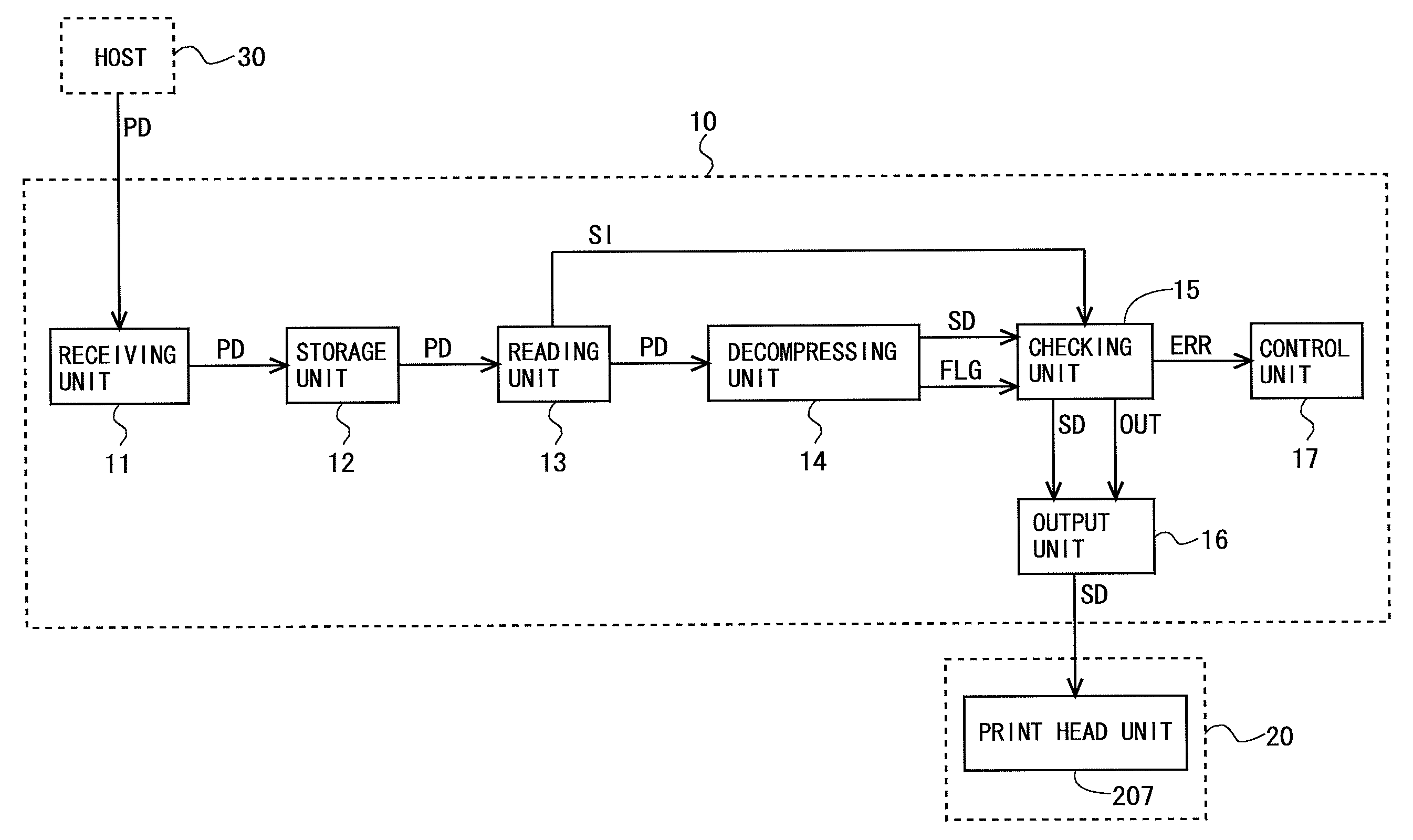
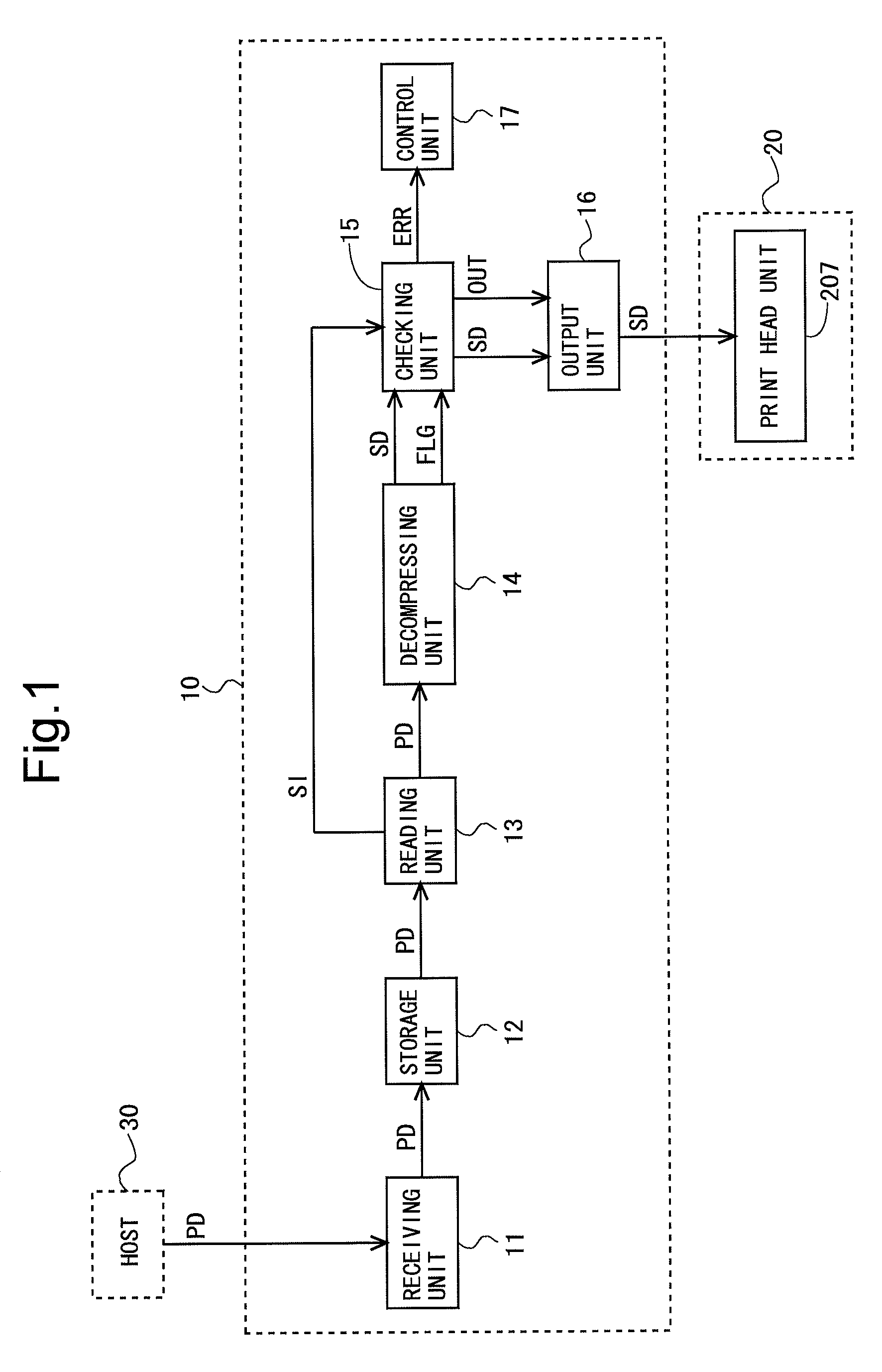
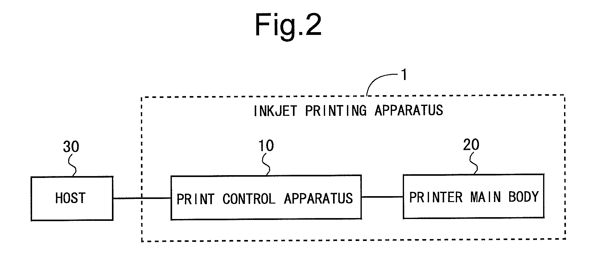
[0072]FIG. 2 is a block diagram showing a configuration of an entire printing system according to an embodiment of the present invention. The printing system is configured by an inkjet printing apparatus 1 and a host 30. The inkjet printing apparatus 1 is configured by a printer main body 20 and a print control apparatus 10 which is a control apparatus for the printer main body 20. In the printing system, the host 30 functions as a transfer apparatus that transfers compressed data to be printed (hereinafter, referred to simply as “compressed data”) to the print control apparatus 10. More specifically, the host 30 converts data to be printed from a vector format to a raster format by a RIP (Raster Image Processor), and performs run-length compression, e.g., a PackBits scheme, on the converted data, thereby obtaining compressed data. Then, the host 30 transfers the co...


PUM


Abstract

Compressed data transmitted to a print control apparatus includes break data having information on a compressed size and a decompressed size for each page. When the compressed data is transferred to a decompressing unit, the break data is converted to NOP data. Information on the decompressed size included in each break data is provided to a checking unit. During a period in which a decompression process is performed, a decompression flag is turned on. The checking unit obtains the actual decompressed size by counting a period in which the decompression flag is turned on, to check whether the decompression process has been normally performed. During a period in which the decompressing unit and the checking unit perform processes for a certain page, a reading unit reads compressed data for the next page.

Description

BACKGROUND OF THE INVENTION[0001]1. Field of the Invention[0002]The present invention relates to a print control apparatus that generates data for print output by performing a decompression process on compressed data.[0003]2. Description of Background Art[0004]Conventionally, there is known a printing system configured by a printing apparatus such as an inkjet printing apparatus; and a host (typically, a computer called a “server”) which is a transmission source of print data. In such a printing system, when comparing the data transfer rate between the host and the printing apparatus with the printing speed of the printing apparatus, generally, the printing speed of the printing apparatus is higher. Therefore, when image data to be printed is transmitted to the printing apparatus from the host as it is, the printing apparatus cannot perform printing at its original printing speed (the printing apparatus needs to stop printing at times). Hence, when performing printing, compressed im...

Claims


Application Information

Patent Timeline
Patent Type & Authority Patents(United States)
IPC IPC(8): G06K15/02G06K15/12
CPCG06K15/02G06K15/1817G06K15/1807G06K15/181G06K15/12
Inventor SHIMIZU, KATSUHISA
Owner DAINIPPON SCREEN MTG CO LTD
Why Eureka
Try Eureka