Check patentability & draft patents in minutes with Patsnap Eureka AI!

Head-mounted display

a display and head technology, applied in the field of displays, can solve the problems of insufficient clarity of the image formed on the retina of the human eye, inability to clearly see the object, and bulky hmd, etc., and achieve the effect of reducing the distance between the transmissive type display and the human ey

Active Publication Date: 2015-02-24
WISTRON CORP
View PDF3 Cites 8 Cited by
  • Summary
  • Abstract
  • Description
  • Claims
  • Application Information

AI Technical Summary

Benefits of technology

The invention is about a type of display that can be seen through a special lens in a head-mounted display (HMD). The display is placed close enough to the human eye that it can capture images on the retina. This allows for a smaller distance between the display and the human eye, while still ensuring clear images are observed. The technical effect of this is improved image quality and more immersive visual experiences for the user wearing the HMD.

Problems solved by technology

When a distance to a to-be-observed object is shorter than the minimum visible distance of the human eye, i.e., when the object is overly close to the human eye, the image of the object formed on a retina of the human eye is of insufficient clarity.
Hence, the human eye is not able to see the object clearly.
Said HMD, however, is bulky and is difficult to be worn by a user.
If the volume of the HMD is reduced by shortening the distance between the HMD and the human eye, the human eye can barely see the image with clarity; what is more, the overly short distance may lead to contraction of ciliary muscle over a long period of time, and thereby the problem of eye fatigue or blurred vision may occur.

Method used


Image

  • Head-mounted display
  • Head-mounted display
  • Head-mounted display

Examples


Embodiment Construction

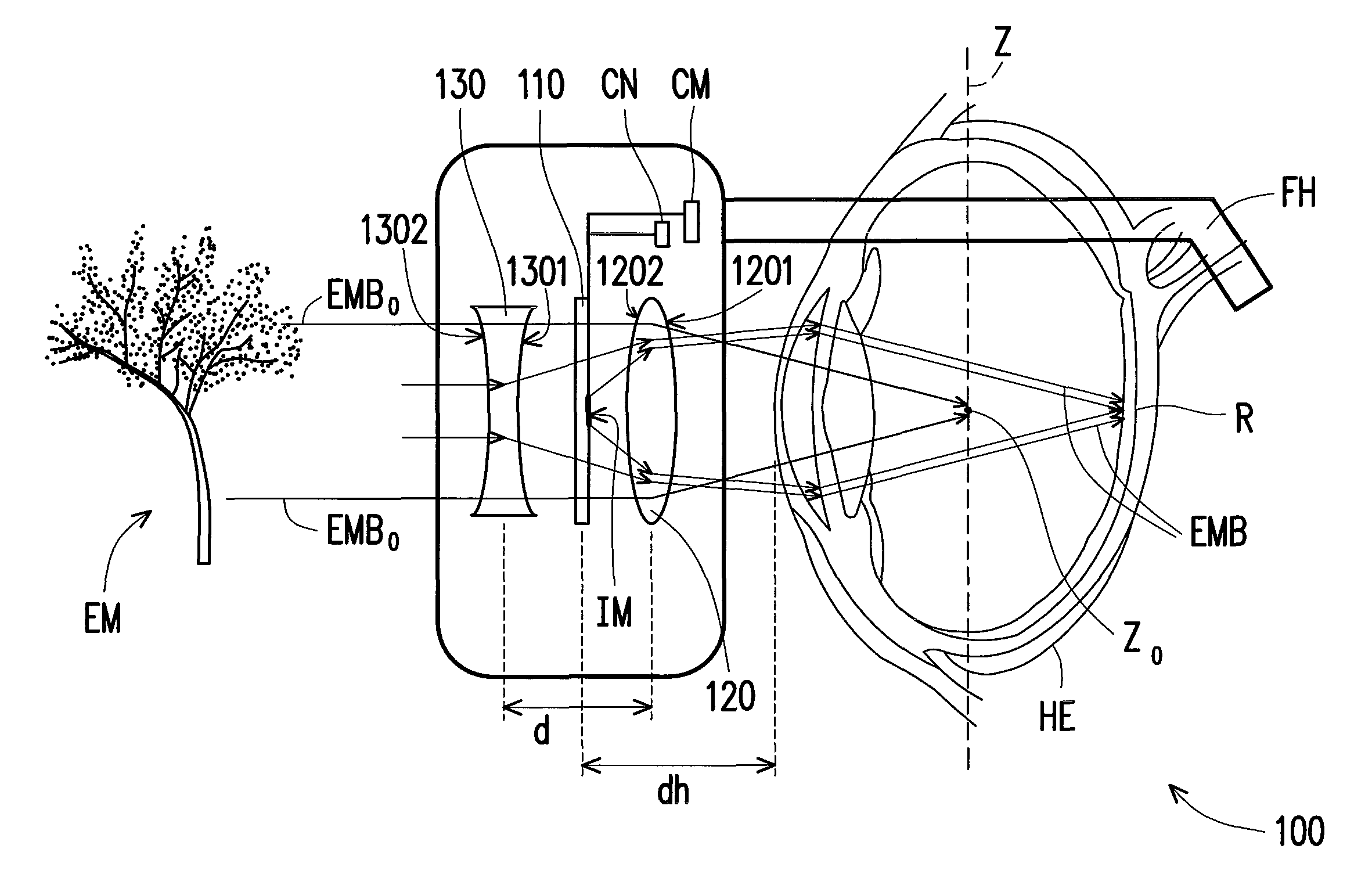
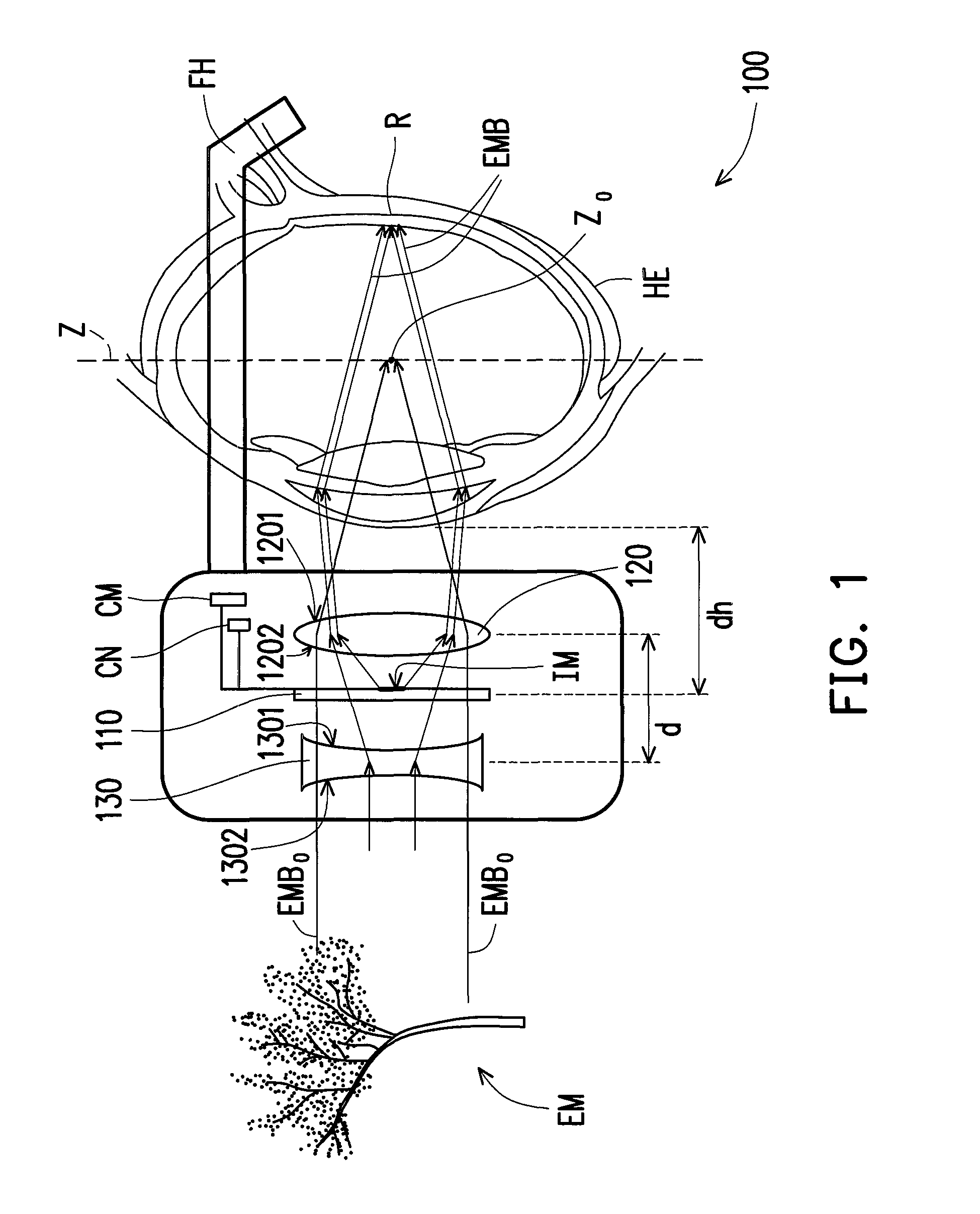
[0034]FIG. 1 is a schematic view illustrating a head-mounted display (HMD) according to an embodiment of the disclosure. With reference to FIG. 1, in the present embodiment, an HMD 100 suitable for being disposed in front of at least one human eye HE is provided, and the HMD 100 includes a transmissive type display 110, a focal length adjusting lens 120, and a compensation lens 130. The focal length adjusting lens 120 is located between the human eye HE and the transmissive type display 110 and refracts an image IM displayed by the transmissive type display 110, such that the image IM is formed on a retina R of the human eye HE. The focal length adjusting lens 120 is a convex lens; in the present embodiment, the focal length adjusting lens 120 is a biconvex lens, for instance, which should however not be construed as a limitation to the disclosure. In another embodiment, the focal length adjusting lens 120 may be a plane-convex lens. The compensation lens 130 is a concave lens; in t...


PUM


Abstract

A head-mounted display suitable for being disposed in front of at least one human eye is provided. The head-mounted display includes a transmissive type display, a focal length adjusting lens, and a compensation lens. The focal length adjusting lens is located between the human eye and the transmissive type display. The focal length adjusting lens refracts an image displayed by the transmissive type display, so that the image is formed on a retina of the human eye. The transmissive type display is located between the compensation lens and the focal length adjusting lens.

Description

CROSS-REFERENCE TO RELATED APPLICATION[0001]This application claims the priority benefit of Taiwan application serial no. 101145275, filed on Dec. 3, 2012. The entirety of the above-mentioned patent application is hereby incorporated by reference herein and made a part of this specification.BACKGROUND OF THE DISCLOSURE[0002]1. Field of the Disclosure[0003]The disclosure relates to a display; more particularly, the disclosure relates to a head-mounted display (HMD).[0004]2. Description of Related Art[0005]With the continuous progress of displays or display-related technologies, the displays tend to be become light and compact to satisfy users' requirements for portability of the displays. For instance, a head-mounted display (HMD) is one of the light and compact displays. The HMD normally allows a user to observe a video signal through a pair of glasses, a pair of goggles, or a wearable helmet. Due to the inherent limitations of crystalline lens and ciliary muscle of a human eye, the...

Claims


Application Information

Patent Timeline
Patent Type & Authority Patents(United States)
IPC IPC(8): G02B27/14G02B7/04G02B27/01
CPCG02B27/0172G02B2027/0127G02B2027/0178
Inventor CHANG, YAO-TSUNG
Owner WISTRON CORP
Features
  • R&D
  • Intellectual Property
  • Life Sciences
  • Materials
  • Tech Scout
  • Unparalleled Data Quality
  • Higher Quality Content
  • 60% Fewer Hallucinations
Learn More