
Session relay equipment and session relay method

a technology of relay equipment and relay method, which is applied in the field of equipment and a relay method for relaying a tcp (transmission control protocol) session, can solve the problems of increasing communication traffic, affecting the service life of current users, and unable to meet the needs of current users who demand advanced communication services. achieve the effect of smooth and comfortable packet-transmitting/receiving operation

Active Publication Date: 2015-02-24
NEC CORP
View PDF10 Cites 0 Cited by
  • Summary
  • Abstract
  • Description
  • Claims
  • Application Information

AI Technical Summary

Benefits of technology

The present invention provides session relay equipment and methods that offer a smooth and comfortable way for users to operate in Tarapan session. This equipment can provide high-speed internet and various communication services, such as QoS and security, to users. This allows for a seamless and comfortable experience for user's in transmitting and receiving packets during a TCP session.

Problems solved by technology

Meanwhile, problems such as the lack of guarantee of communication quality, threats to security, and the growth of communication traffic, have arisen.
However, while the Internet is spreading in this way, the needs of current users who demand advanced communication services cannot be satisfied.
Since the current Internet is originally an Internet service of “Best Effort” (a communication service without controlling QoS (Quality of Service)), it is not suitable to be applied to businesses and “Rich Contents” on a full scale.
In the above described conventional communication network system, however, a high-speed communication service is not provided to its users.
However, a system capable of implementing such process has not been provided until now.
And the proxy in the RFC 3135 does not have any socket information table or service information table, so the proxy can not selectively terminate the TCP packet from the one end system or provide any types of communication services.

Method used


Image

  • Session relay equipment and session relay method
  • Session relay equipment and session relay method
  • Session relay equipment and session relay method

Examples


Embodiment Construction

[0026]An embodiment of the present invention will now be described with reference to the accompanying drawings.

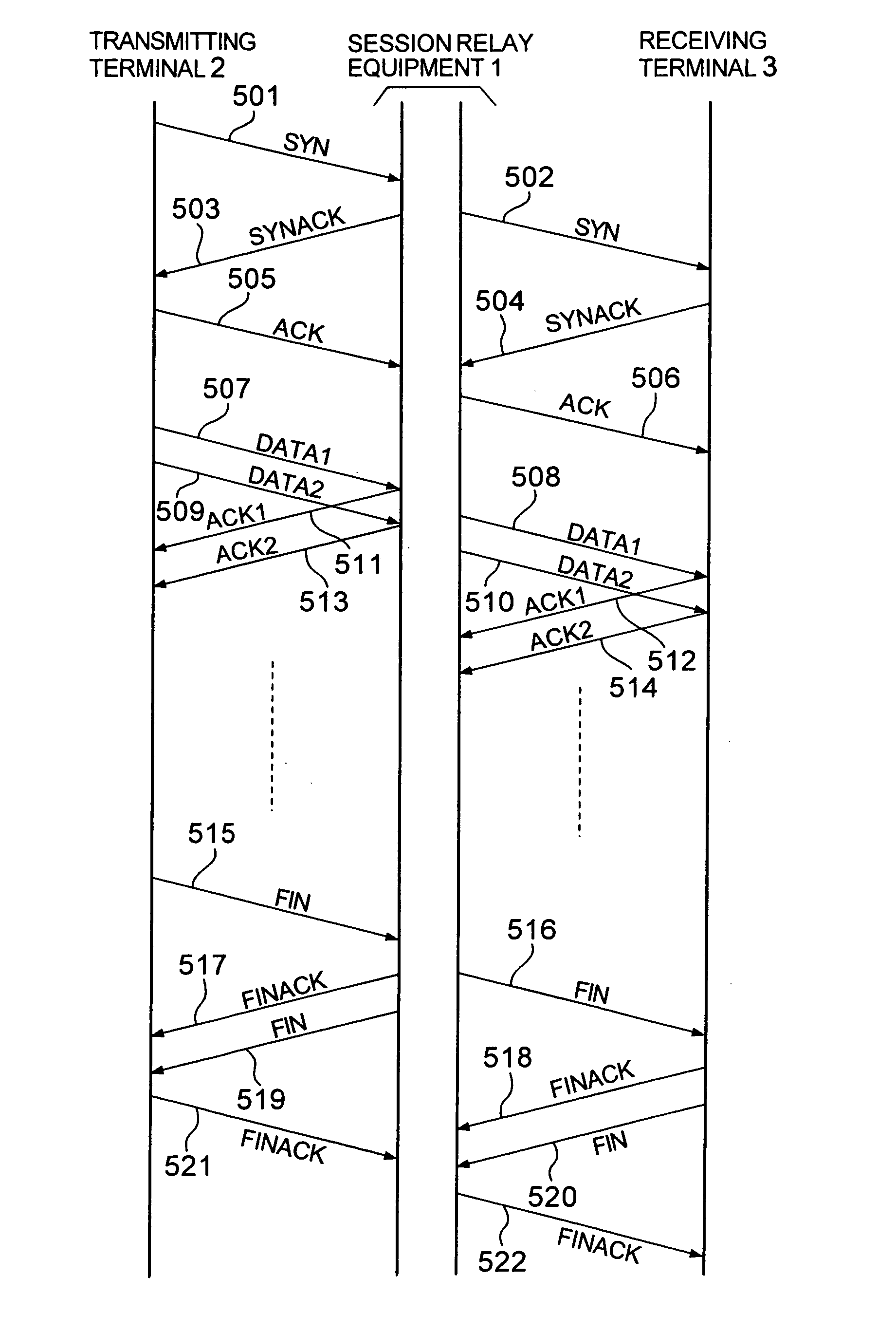
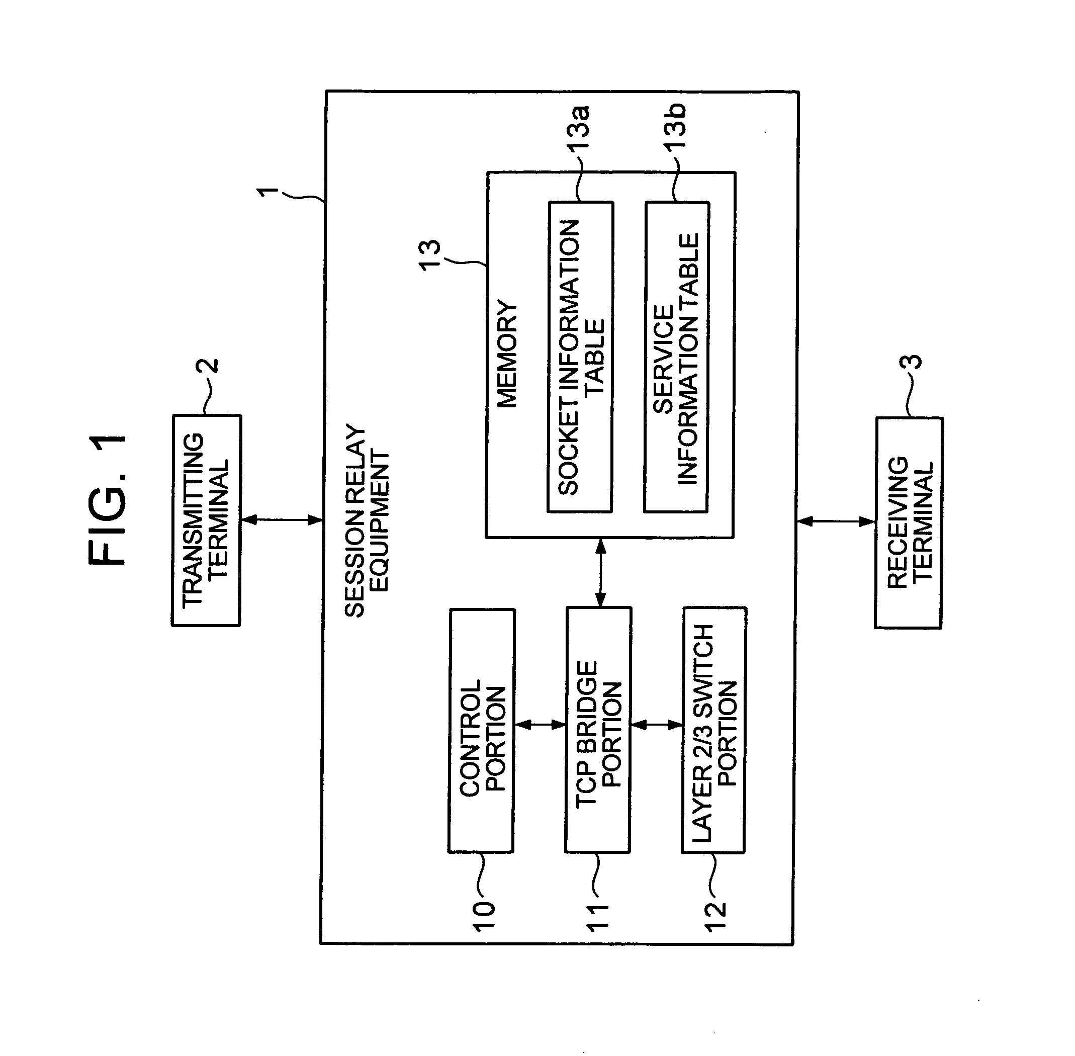
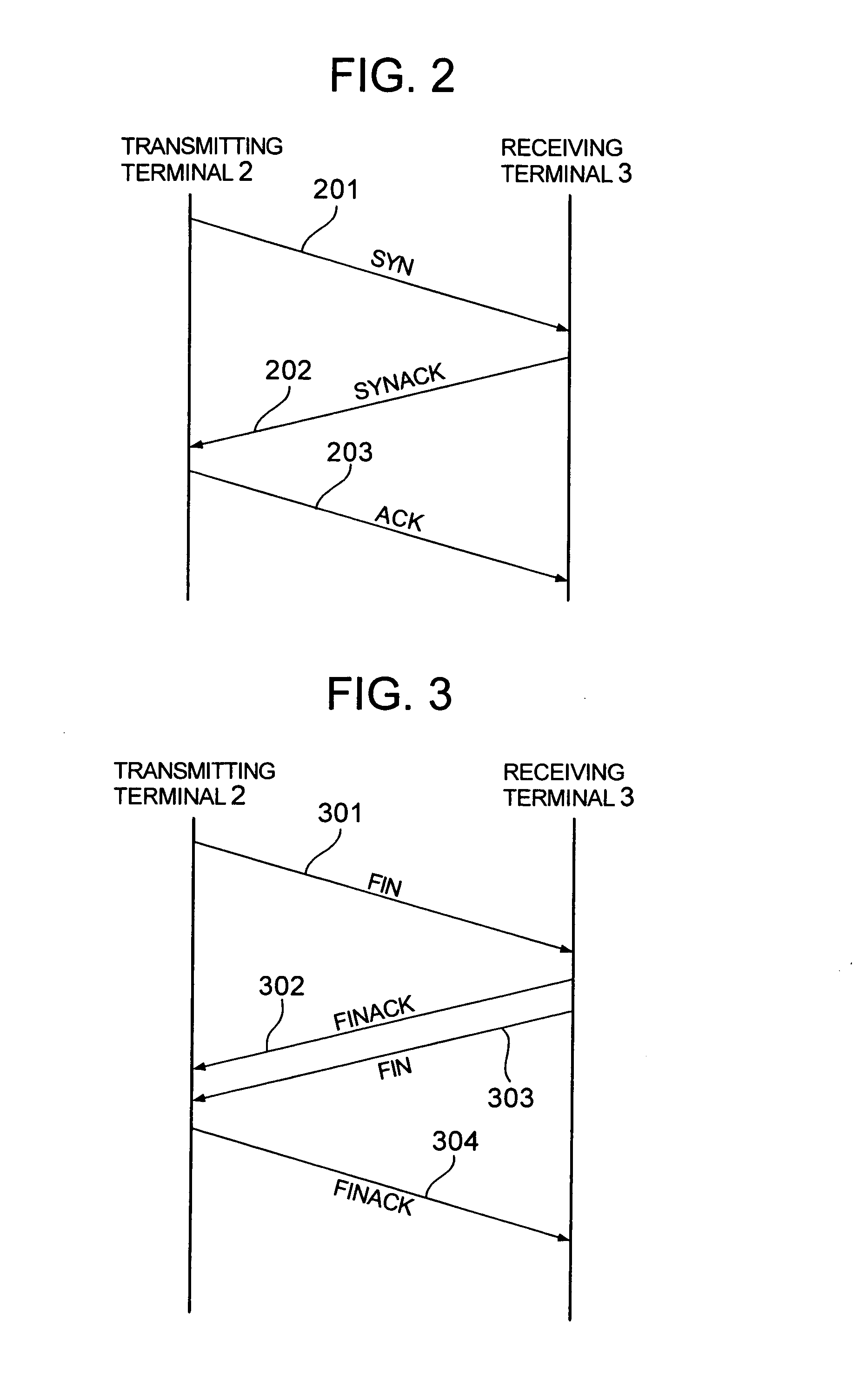
[0027]FIG. 1 is a block diagram showing a schematic configuration of the session relay equipment according to one embodiment of the present invention. In the drawing, parts which are not directly necessary for the description of the present invention are omitted. Referring to FIG. 1, the session relay equipment 1 relays a session by which a sequence of packets are transmitted and received between a transmitting terminal 2 and a receiving terminal 3 connected with each other via a network (specifically, a line provided by a carrier, or a network provided by an ISP or a telecommunications firm). Herein, the word “session” means a TCP session (packet) based on TCP (Transport Control Protocol) / IP (Internet Protocol) being a standard protocol used in the Internet. Communication by TCP / IP is divided into Physical Layer (Layer 1), Data Link Layer (Layer 2), Internet Layer (Layer 3...


PUM


Abstract

A network environment capable of performing a smooth and comfortable TCP session operation is provided to a user. The session relay equipment includes a bridge portion which relays a session by which a sequence of packets are transmitted and received between terminals connected with each other via a network; a socket information table which has socket information containing (1) address information of the terminal and (2) protocol information used in the session, the socket information being associated with information on whether or not the session is to be terminated; and a service information table which has information on a communication service to be provided for each service provision unit, the communication service being identified based on predetermined information within a header of the packet. The bridge portion terminates the session and executes a communication service based on the information contained in the header of the packet and the socket information.

Description

BACKGROUND OF THE INVENTION[0001]1. Field of the Invention[0002]The present invention relates to equipment and a method for relaying a TCP (Transmission Control Protocol) session.[0003]2. Description of the Related Art[0004]In recent years, as the Internet is rapidly spreading, a variety of businesses and services using the Internet are being provided. Meanwhile, problems such as the lack of guarantee of communication quality, threats to security, and the growth of communication traffic, have arisen.[0005]Currently, carriers, telecommunications firms and ISPs (Internet Service Providers) which provide service using the Internet each provide a network service using network equipment such as a switch and router which are based on TCP / IP (Internet Protocol). Using this infrastructure, they endeavor to increase the number of access points and broaden the line bandwidth, thereby spreading and improving the Internet.[0006]However, while the Internet is spreading in this way, the needs of ...

Claims


Application Information

Patent Timeline
Patent Type & Authority Patents(United States)
IPC IPC(8): H04L12/28H04J1/16H04L12/66
CPCH04L12/66
Inventor SHIBATA, GOHKAWABATA, ATSUSHIASANO, YUKOMURASE, TUTOMUSHIMONISHI, HIDEYUKIHASEGAWA, YOHEIYAMAZAKI, YASUHIRO
Owner NEC CORP
Learn More