Pull-push type rope locking device

A rope lock and splint technology, applied in the direction of transmission elements or pulley ropes or cables, textile cables, belts/chains/gears, etc. problems, to achieve the effect of small damage, small change in the included angle, and stable operation

Active Publication Date: 2015-11-25
刘明
View PDF11 Cites 0 Cited by
  • Summary
  • Abstract
  • Description
  • Claims
  • Application Information

AI Technical Summary

Problems solved by technology

[0004] The purpose of this patent is to solve the problem that the original structure of the rope lock will obviously reduce the service life of the wire rope and the supporting wheel, and the operation will be unstable and shake, and the impact and noise will cause environmental pollution and safety hazards, and an unreliable problem was invented. pull-push rope lock

Method used


Image

  • Pull-push type rope locking device
  • Pull-push type rope locking device
  • Pull-push type rope locking device

Examples


Embodiment Construction

[0035] The present invention will be further described below in conjunction with accompanying drawing and specific embodiment:

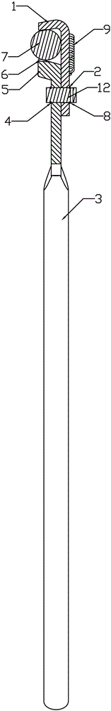
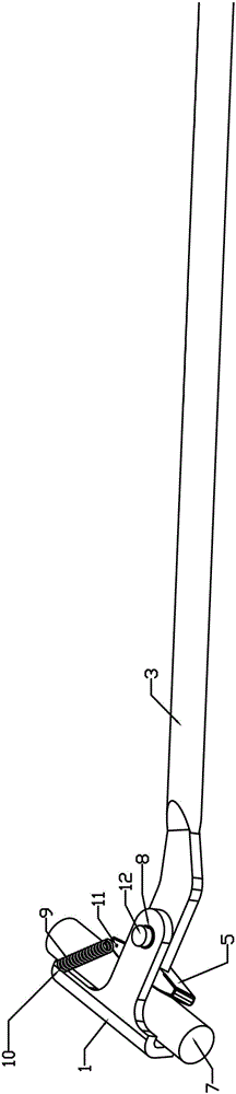
[0036] A pull-push type rope lock, including: a splint 1 and a handle 3. The characteristic is that: the splint 1 and the chuck 5 on the handle 3 form a leverage force through the connecting shaft 12, which can be between the splint 1 and the chuck 5 Lock and clamp the wire rope 7 and the like by applying a pulling force to the handle 3, or release the pulling force on the handle 3 or apply force in the opposite direction, and easily remove the push-pull rope lock from the wire rope . Before using, the return spring 9 keeps a state between the splint 1 and the handle chuck 5 all the time.

[0037] There are anti-slip protrusions on the splint 1 and the chuck 5, and a splint shaft hole 2 and a handle shaft hole 4 are respectively designed on the splint 1 and the handle 3, and the splint 1 can be C-shaped or L-shaped.

[0038] Clamp plate 1 and handl...


PUM


Abstract

A pull-push type rope locking device comprises a handle and is characterized in that a chuck is arranged at one end of the handle, and a clamping plate is arranged at the end, close to the chuck, of the handle. The clamping plate and the handle are connected through a connecting shaft. A reset spring is arranged between the chuck and the clamping plate. The clamping plate is provided with a clamping plate shaft hole. The handle is provided with a handle shaft hole. The connecting shaft penetrates the clamping plate shaft hole and the handle shaft hole so that the clamping plate can be hinged to the handle, and the upper end and the lower end of the connecting shaft are fixed through C-shaped clips respectively. The clamping plate and the handle are provided with a clamping plate reset hole and a handle reset hole respectively, and the reset spring is fixed to the clamping plate reset hole and the handle reset hole so that the pull-push type rope locking device can be maintained in a standby state. The chuck is provided with a chuck anti-skid protrusion, and the clamping plate is in a C shape or an L shape and is provided with an anti-skid protrusion. The clamping plate and the handle are coated with light reflecting materials for improving the warning effect. The clamping plate and the handle are made of metal materials or high-strength non-metal polymer materials.

Description

technical field [0001] This patent relates to a quick lock and release device. While maintaining a certain tension, it can simply and quickly clamp and lock linear objects or quickly release them. If the linear objects are moving, they can be clamped Or loosen the pull-push type rope lock for transporting objects in linear objects. Background technique [0002] At present, in some long inclined tunnels underground in coal mines, going up and down for a long time will consume a lot of physical strength of the staff. In order to save the physical strength of the personnel, equipment such as hanging monkeys or rickshaws are generally installed to reduce the physical exertion of the personnel. However, due to cost, Affected by factors such as distance, environment, efficiency, space, and safety, some places are not suitable for the use of the above equipment. In order to reduce the physical exertion of underground personnel climbing uphill and save time, a simple, light, low-cos...

Claims


Application Information

Patent Timeline
Patent Type & Authority Applications(China)
IPC IPC(8): F16G11/10
CPCF16G11/105
Inventor 刘明王晨付晓光
Owner 刘明
Why Eureka
Try Eureka