Ball joint with a sealing bellow

A spherical universal joint and spherical pivot technology, applied in the directions of shafts and bearings, suspensions, pivots, etc., can solve the problems of increased cost, troublesome, damage to the sealing effect of the sealing box and the spherical pivot, etc., to achieve tightness beneficial effect

Inactive Publication Date: 2007-08-29
ZF FRIEDRICHSHAFEN AG
View PDF1 Cites 6 Cited by
  • Summary
  • Abstract
  • Description
  • Claims
  • Application Information

AI Technical Summary

Problems solved by technology

On the one hand, this is complicated and expensive, and on the other hand, it also impairs the sealing effect between the sealing box and the spherical pivot
[0010] Due to the arrangement of one end of the compression spring on the joint housing, the compression spring is also dynamically loaded whenever the ball joint moves, which must be taken into account in the durability design of the compression spring and leads to a correspondingly larger dimension of the compression spring. spring or a corresponding increase in costs due to the necessary use of high-value materials for the compression spring
Finally, a compression spring arranged in this way also clearly has a negative effect on the maximum possible angular deflection of the ball joint
Because when the compression spring presses against the component on one side, no further angular movement of the universal joint housing in the corresponding deflection direction relative to the spherical pivot can be achieved

Method used


Image

  • Ball joint with a sealing bellow
  • Ball joint with a sealing bellow
  • Ball joint with a sealing bellow

Examples


Embodiment Construction

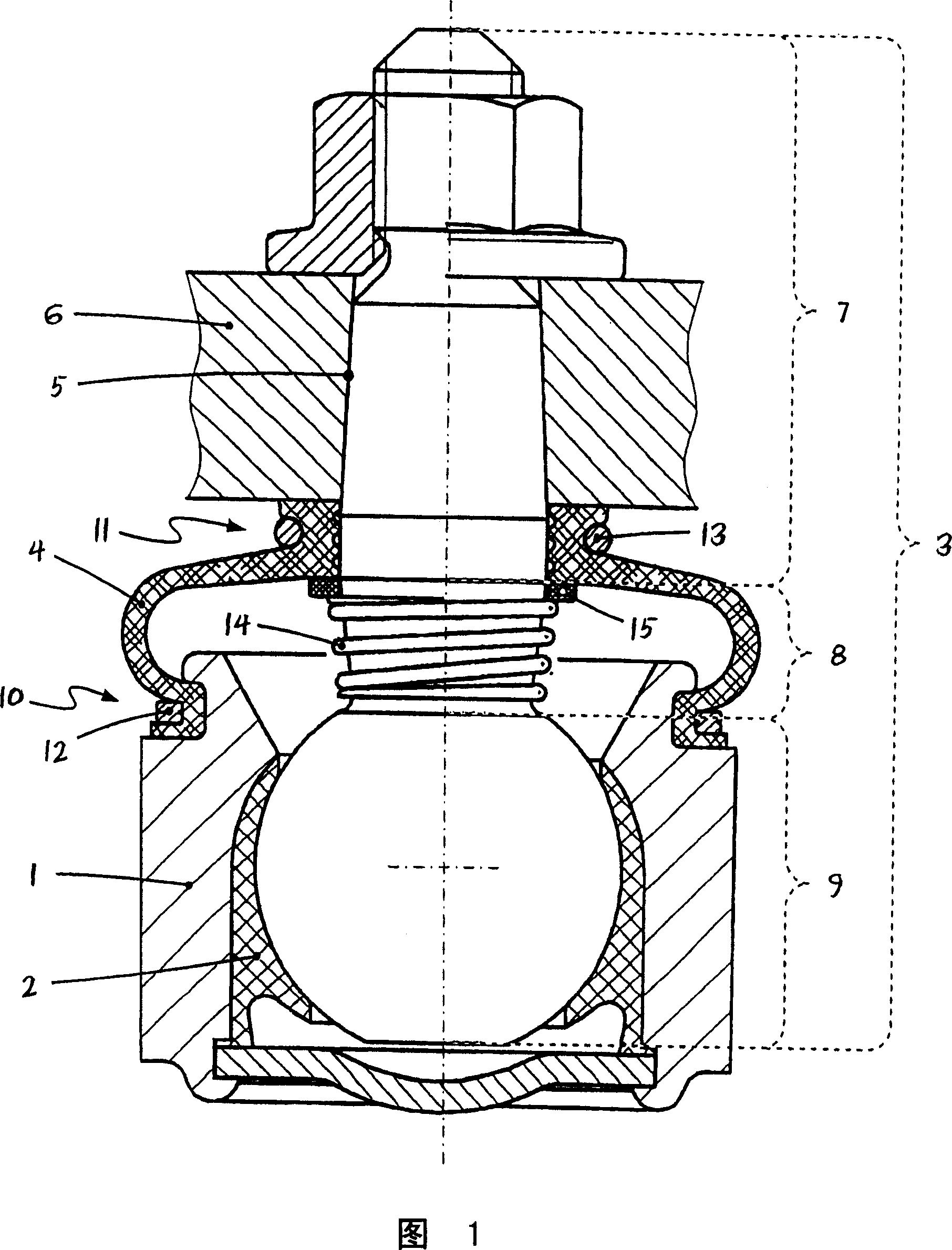
[0042] FIG. 1 shows a first embodiment of a ball joint according to the invention. First, the main components of the ball joint can be seen, namely the joint housing 1 with the bearing housing 2 arranged therein as well as the ball pivot 3 and the sealing box 4 . At the upper part of the spherical pivot 3 with reference to the drawing, this spherical pivot 3 is screwed, for example, with a lever ring 5 of a push rod 6 or the like. However, position 6 can also be a chassis component, such as a transverse guide rod, or an axial component, such as a swivel bearing, wheel carrier or the like. The spherical pivot 3 consists of a shank area 7 , a neck area 8 and a ball 9 .

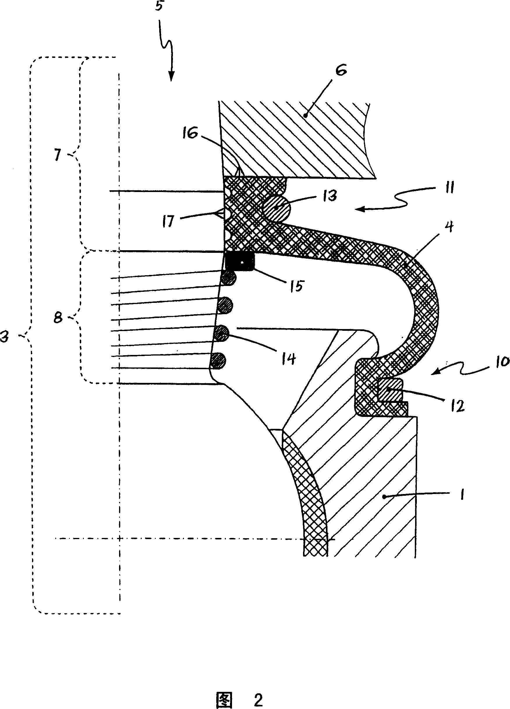
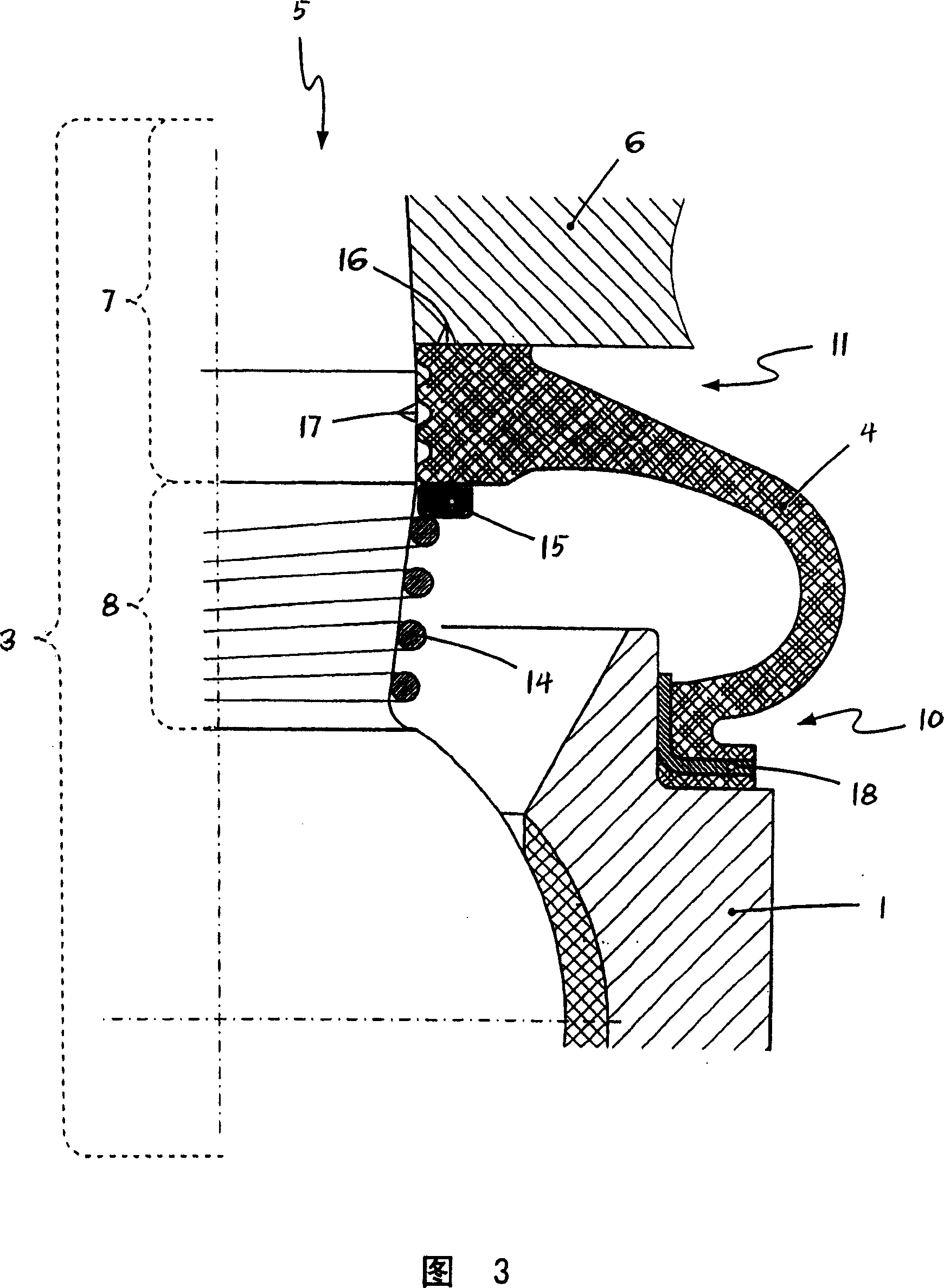
[0043] It can also be seen that the sealing box 4 has two connecting straps 10 , 11 which form the connection of the sealing box 4 at the joint housing 1 or at the stem region 7 of the ball pivot 3 . In the exemplary embodiment shown, the two connecting straps 10, 11 each have a clamping ring 12, 13, which sup...


PUM


Abstract

The invention relates to a ball joint with a sealing bellow (4), whereby the sealing bellow (4) is arranged on the surface (17) of the ball pivot (3) in the shaft region (7) of the ball pivot (3), by means of a surrounding end band (11). The ball joint is characterised in that an elastic element (14), in the axial direction of the journal, which can be embodied in the form of a pressure spring element is arranged in the neck area (8) of the ball pivot (3). The pressure spring element presses against one end in the region of the transition between the neck area (8) and the ball (9) of the ball journal (3) and on the other end, directly or indirectly on the journal side of the end band (11) of the sealing bellow (4). The invention also relates to a ball joint wherein the sliding of the sealing bellow on the neck of the ball journal is prevented in a durable and reliable manner, even under extreme climatic conditions, or during exceptional mechanical stresses, such as, the impingement of a water jet of a high pressure cleaning device. Also, the journal-sided sealing of the sealing bellow and the constructive control and dimensioning of said ball joint is improved.

Description

technical field [0001] The invention relates to a ball joint with a sealing box according to the preamble of claim 1 . Background technique [0002] Ball joints of the type described above are used, for example, but not exclusively, in the running gear or wheel suspension of automobiles. [0003] Such a ball joint is known, for example, from US Pat. No. 2,397,464. Ball joints of this type have a joint housing, wherein a bearing housing for slidingly accommodating a joint ball arrangement arranged on a spherical pivot is inserted in the joint housing interior. The spherical pivot is connected or bolted in a conventional manner to a connecting part, for example to a lever collar of a steering column on a motor vehicle. [0004] In order to prevent moisture and / or dirt from penetrating into the bearing area of ​​the ball joint, this known ball joint has a sealing box made of elastomer material, which has two annular connecting bands . The sealing box is connected in a conve...

Claims


Application Information

Patent Timeline
Patent Type & Authority Applications(China)
IPC IPC(8): F16C11/06
CPCY10T403/32729F16C11/0671F16C11/0604F16C11/0628F16C2326/05F16C11/06
Inventor K·布罗克D·阿达姆齐克
Owner ZF FRIEDRICHSHAFEN AG
Why Eureka
Try Eureka