Capturing device, capturing system, and capturing method

a technology which is applied in the field of capturing device and capturing system, and capturing method, can solve the problems of difficult detection of localized images, time-consuming and laborious, and inability to accurately recognize spots in images. achieve the effect of complex configuration

Inactive Publication Date: 2015-03-03
SONY CORP +1
View PDF11 Cites 0 Cited by
  • Summary
  • Abstract
  • Description
  • Claims
  • Application Information

AI Technical Summary

Benefits of technology

[0007]In addition, in existing capturing systems, the definition of the image is determined depending on a transmission capacity of the harness, so that when the image is enlarged by the ECU disposed at the rear end of the camera, the image becomes rough. Moreover, the ECU has to load the full image transferred from the camera in the memory first, so that a component for the image memory is mounted on the capturing system, and a component for a synthesizing process is provided. Accordingly, the number of components for configuring the capturing system is increased, so that the capturing system has a complex configuration and thus becomes expensive.
[0008]It is desirable to allow a driver (user) to easily see an image of a localized spot that the driver particularly wants to see and an image in the vicinity thereof.

Problems solved by technology

In a wide-angle image, detailed recognition of a localized image is difficult.
In addition, although a particular spot that is desired to be preferentially viewed exists, the spot may not be recognized in detail in the image as it is or it may take time to recognize the spot.
In addition, in existing capturing systems, the definition of the image is determined depending on a transmission capacity of the harness, so that when the image is enlarged by the ECU disposed at the rear end of the camera, the image becomes rough.
Accordingly, the number of components for configuring the capturing system is increased, so that the capturing system has a complex configuration and thus becomes expensive.

Method used


Image

  • Capturing device, capturing system, and capturing method
  • Capturing device, capturing system, and capturing method
  • Capturing device, capturing system, and capturing method

Examples


embodiment

1. Embodiment

Example of the Entire Configuration of Capturing System

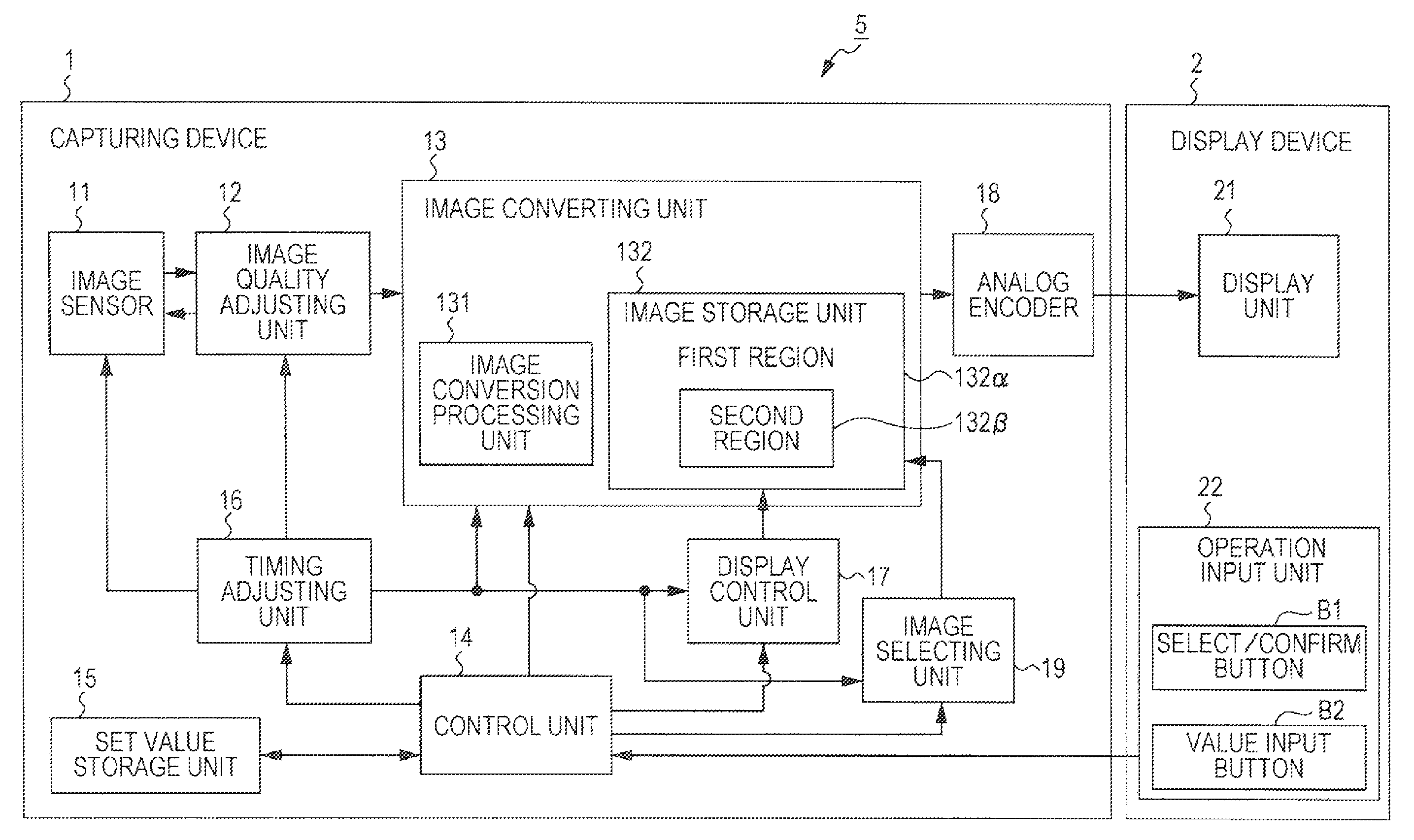
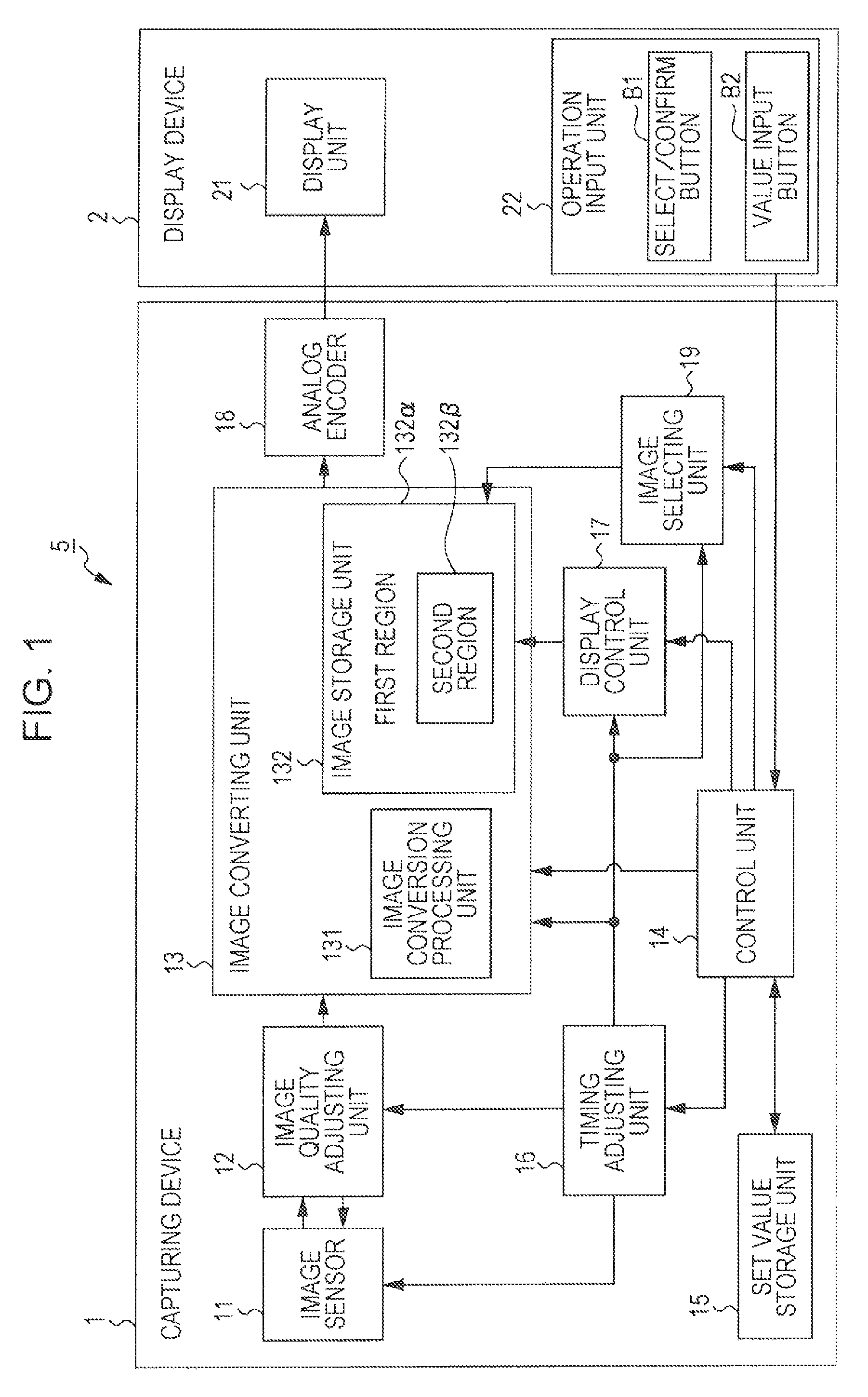
[0032]FIG. 1 is a diagram illustrating an example of configurations of a capturing device 1 and a display device 2 in a capturing system 5 according to an embodiment of the invention. According to the embodiment, the capturing device 1 exemplifies a vehicle-mounted camera which is mounted on the rear of the vehicle (not shown), and the display device 2 exemplifies a display device such as a car navigation device mounted on the vehicle. The capturing device 1 and the display device 2 are connected via a cable (not shown) or the like, and capturing system 5 is configured so that an image signal is input from the capturing device 1 to the display device 2 and a control signal is input from the display device 2 to the capturing device 1.

[0033]Moreover, according to the embodiment, an example in which the capturing device 1 is mounted on the vehicle is shown. However, the embodiment is not limited to this. That is, the c...


PUM


Abstract

A capturing device includes: an image sensor generating an image signal; a storage unit setting a second region in a first region; a timing adjusting unit adjusting a timing at which the image signal is read out to write the image signal in the storage unit, and a timing at which the image signal is read out from the storage unit; an image conversion processing unit performing a predetermined process on the image, alternately writing a first image signal corresponding to a full image or a second image signal corresponding to a partial image in the first region in a different frame period, and writing an image signal that is different from the image signal written in the first region in the second region; and an output unit converting and outputting the first and second image signals into an image signal in a predetermined format.

Description

BACKGROUND OF THE INVENTION[0001]1. Field of the Invention[0002]The present invention relates to a capturing device, a capturing system, and a capturing method which are suitable to be applied to, for example, a vehicle-mounted camera for capturing and displaying a location that is difficult for a driver of a vehicle to see.[0003]2. Description of the Related Art[0004]In the related art, a small camera is mounted on a vehicle, a rail vehicle or the like to display images taken by the camera on a display device provided in the vicinity of a driver's seat or the like (for example, refer to Japanese Unexamined Patent Application Publication Nos. 2002-19556 and 2010-33108). Using such a camera, spots that are difficult for a driver to see while driving are captured, and images of the spots obtained are displayed on a display device, thereby allowing the driver to see the spots. As the spots that are difficult for the driver to see, for example, in the case of a vehicle moving backward d...

Claims


Application Information

Patent Timeline
Patent Type & Authority Patents(United States)
IPC IPC(8): H04N5/76H04N5/232
CPCH04N5/23245H04N5/23293H04N23/667H04N23/635
Inventor OBA, EIJIMAIRE, FREDERIC
Owner SONY CORP
Why Eureka
Try Eureka