Method for manufacturing a multi-ribbed wing box of composite material with integrated stiffened panels

a composite material and wing box technology, applied in the direction of stringers, other domestic articles, transportation and packaging, etc., can solve the problems of production cost, operating cost, weight of the structure, etc., and achieve the effect of complex configuration and greater torsional strength

Active Publication Date: 2022-04-05
LEONARDO SPA
View PDF5 Cites 0 Cited by
  • Summary
  • Abstract
  • Description
  • Claims
  • Application Information

AI Technical Summary

Benefits of technology

[0009]In short, the invention is based on the idea of providing a method for manufacturing a wing box for aircraft wherein the wing box comprises a first and a second panel, stiffened with a plurality of longitudinal reinforcement stringers, and a plurality of ribs, arranged transversely, which are subjected to a single curing process. This is made possible by the use, before the curing process, of a plurality of tools, i.e., auxiliary tools, to ensure precise relative positioning of the components, each of said tools comprising a central removable part, which allows the removal of the tools even when the main body is fully assembled.
[0014]By virtue of such a configuration of the tools, it is possible to simply pull the tools out of the assembly before the curing process, whereby a method according to the invention allows the creation of multi-ribbed wing boxes that have a more complex configuration and may also be used for structures that require greater torsional strength compared to the use of a horizontal stabilizer as a wing box.

Problems solved by technology

This conventional configuration is called ‘build-up’ configuration, and is characterized by significant disadvantages in terms of production costs, including: a large number of parts to be manufactured and managed in the production system, a very onerous assembly process due to the large number of holes to be made and fastening members to be installed, as well as the inspections necessary to verify the absence of openings or space between the coupled parts, and the additional activities required during construction to apply any fillers needed to fill the aforesaid gaps, when present.
In addition, the so-called build-up configuration also entails significant drawbacks in the weight of the structure, which are badly tolerated in aeronautical applications, especially due to the increase in the operating cost of the aircraft, i.e. in fuel consumption.
The weight increase for these assemblies is essentially due to the unavoidable presence of holes in the coupling areas between the various elements.
In addition, for composite structures, the weight of the fastening members also has a negative effect, since it is greater than the weight of the portion of material removed.
This technology, while overcoming all the technical problems typical of the build-up configuration mentioned above, is characterized by significant geometric and configuration limitations that limit its applicability to solely horizontal stabilizers of commercial aircraft.
Specifically, multi-spar co-cured wing boxes are not sufficiently competitive, in terms of weight and cost, with respect to wing boxes in build-up configuration for structures for which a high resistance to torsion is required, such as wing boxes and tail unit boxes.
A further technical problem of this technology is that it is not applicable to configurations that provide for the presence, in addition to the spars, of additional reinforcement stringers, for the longitudinal stiffening of the structure.
Furthermore, according to the prior art, it is not possible to make wing boxes with highly curved aerodynamic profiles and / or with inner thickening or stiffening elements in the transverse direction (i.e., that extend in the direction of the length of the wing profile), or with the stringers interrupted in the longitudinal direction (i.e., perpendicular to the direction of the length of the wing profile) of the wing box.
These limitations, which severely compromise the possibility of making the aircraft wing box more efficient from a structural point of view and therefore in terms of weight, are essentially due to the fact that the multi-spar may only be co-cured in configurations wherein it is possible to extract the auxiliary tools, i.e. the tools used for the construction of each cell or bay of the structure.

Method used


Image

  • Method for manufacturing a multi-ribbed wing box of composite material with integrated stiffened panels
  • Method for manufacturing a multi-ribbed wing box of composite material with integrated stiffened panels
  • Method for manufacturing a multi-ribbed wing box of composite material with integrated stiffened panels

Examples


Embodiment Construction

[0023]In the present context, the term ‘longitudinal’ indicates a direction substantially coincident or parallel with that of the main extension of the wing or of the empennage, while the term ‘transverse’ indicates a direction substantially perpendicular thereto, identifiable, in general, with a direction substantially coincident or parallel with that of a wing or empennage profile.

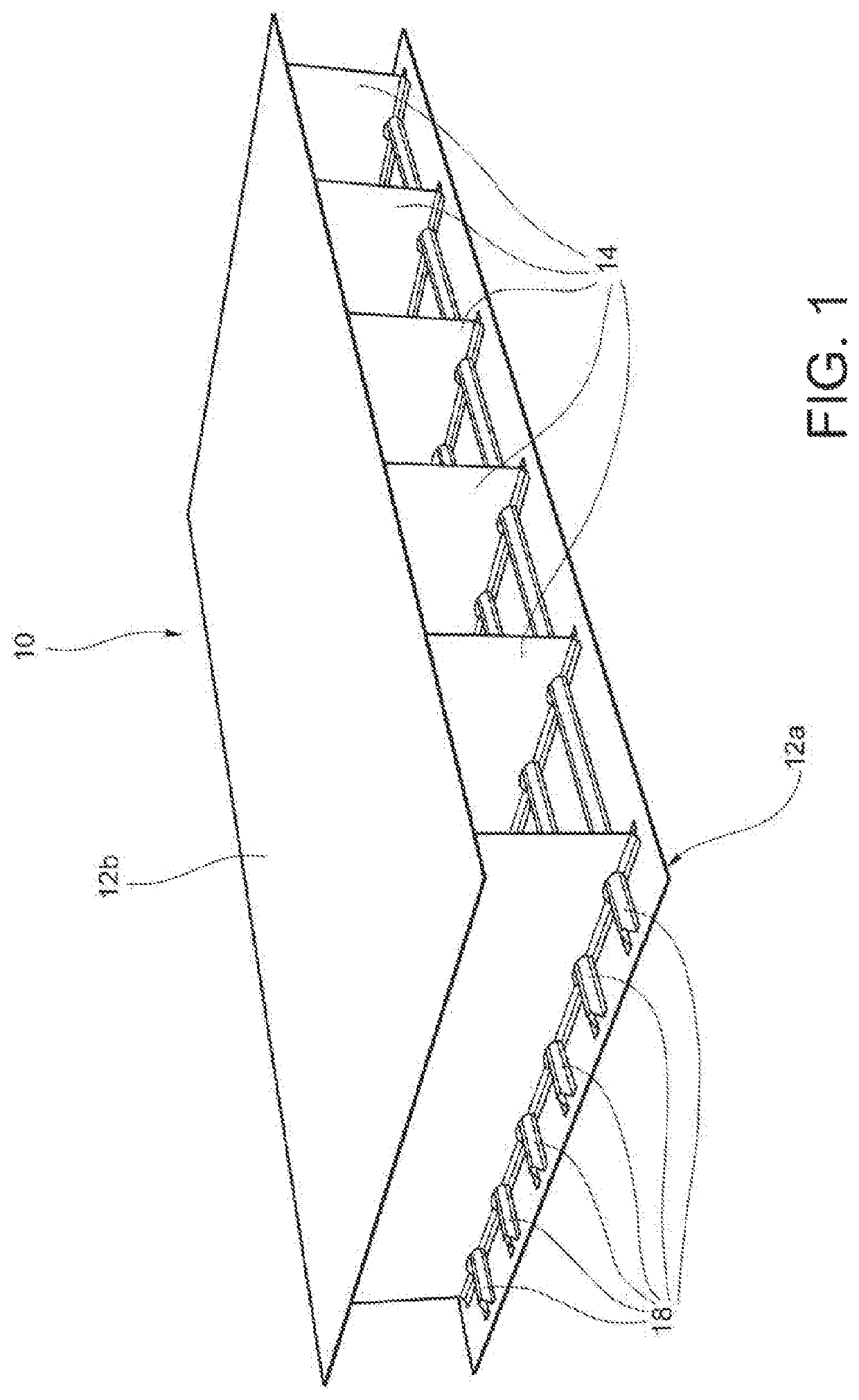
[0024]With reference to the figures, an aircraft wing box as a whole is indicated with 10.

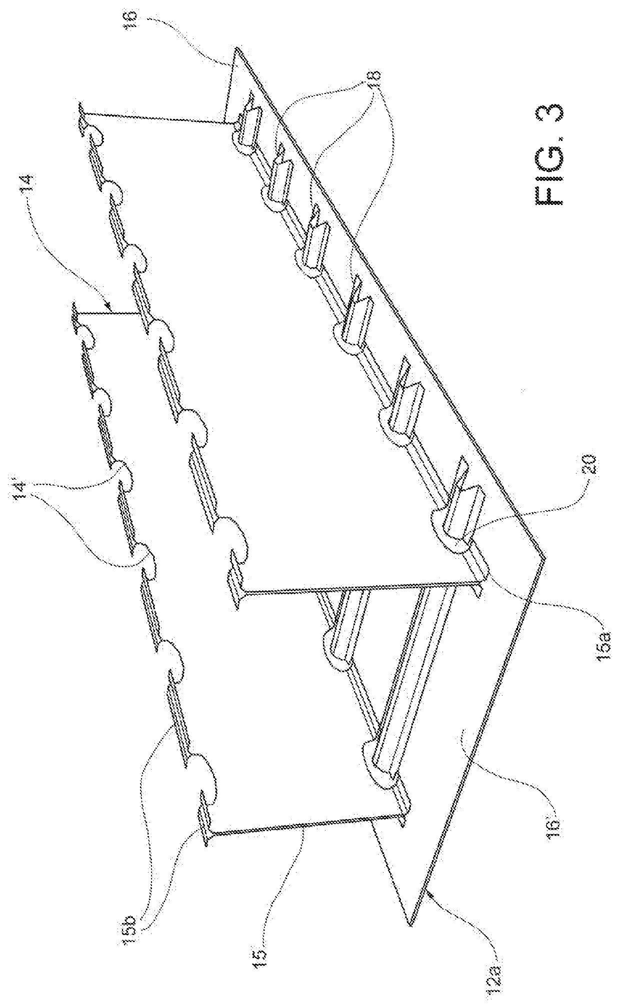
[0025]The wing box 10 comprises a first panel 12a, a second panel 12b, and a plurality of ribs 14.

[0026]The first panel 12a, the second panel 12b and the ribs 14 are made of composite material. Preferably, the composite material comprises a thermosetting or bismaleimide resin matrix and / or a carbon and / or glass fiber reinforcement.

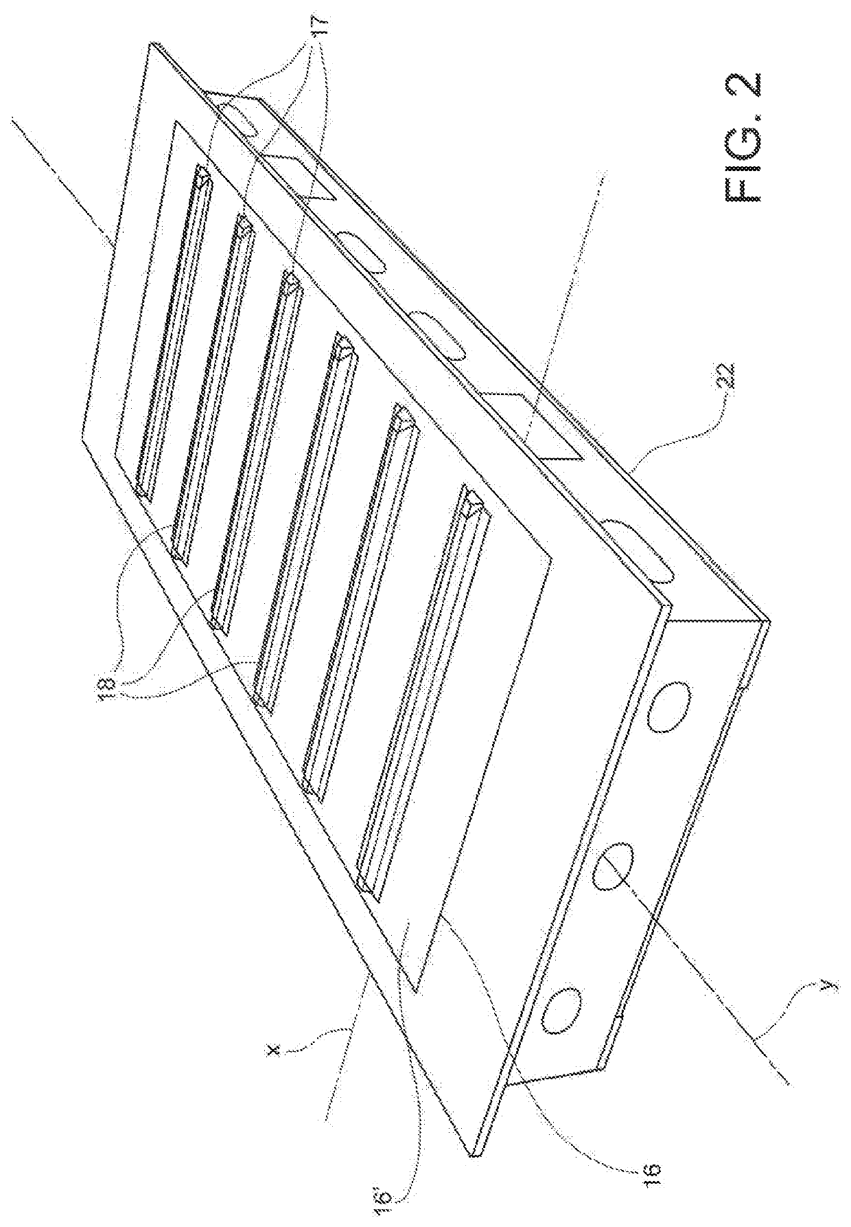
[0027]The first panel 12a and the second panel 12b may be made in a similar way. In this example, for the sake of brevity, only the first panel 12a will be described, it being understood t...


PUM

PropertyMeasurementUnit
lengthaaaaaaaaaa
mass densityaaaaaaaaaa
pressureaaaaaaaaaa

Abstract

A method for manufacturing a wing box for aircraft comprises the steps of arranging, on a curing surface, a first panel of composite material, alternately arranging, on the first panel, along a transverse direction, a rib of non-polymerized composite material and a tool comprising a central part, a bottom part and a top part, wherein the central part of each tool is interposed between said bottom part and the top part and may be extracted in a transverse direction, arranging a second panel of composite material by putting said second panel in contact with the flanges of each rib, pulling out the central part of each tool along the transverse direction and removing the top part and the bottom part of each tool, and subjecting the first panel, the second panel, and each rib to a curing process in autoclave with vacuum bag.

Description

CROSS-REFERENCE TO RELATED APPLICATION[0001]This application claims priority to Italian Patent Application No. 102018000010328 filed Nov. 14, 2018, the entire contents of which is hereby incorporated in its entirety by reference.FIELD OF THE INVENTION[0002]The present invention relates to a method for manufacturing a structural component for aircraft. In particular, the invention relates to a method for manufacturing a multi-ribbed wing box made of composite material with integrated stiffened panels, usable in particular as a structural box in a wing, or in a vertical or horizontal empennage.BACKGROUND OF THE INVENTION[0003]The configuration currently adopted for aeronautical boxes—for wings or empennages of fixed-wing aircraft—consists of a set of different primary structural components, such as, typically, two stiffened panels with longitudinal stringers, two longitudinal spars, a certain number of transverse ribs, angular elements and conventional mechanical fastening elements.[0...

Claims


Application Information

Patent Timeline
Patent Type & Authority Patents(United States)
IPC IPC(8): B64C3/00B64F5/00B29C33/00B29D99/00B64C3/26B64C3/18B64C3/20B64F5/10B29C33/48B29L31/30
CPCB64C3/26B29C33/0033B29C33/485B29D99/0014B64C3/187B64C3/20B64F5/10B29L2031/3085B64C3/182B64C1/00B64C2001/0072Y02T50/40
Inventor IAGULLI, GIANNIRAFFONE, MARCORUSSOLILLO, ALBERTONANULA, TOMMASOTOTARO, GIUSEPPE
Owner LEONARDO SPA
Why Eureka
Try Eureka