
Metal product having internal space formed therein and method of manufacturing thereof

a metal product and internal space technology, applied in the direction of manufacturing tools, shaping tools, transportation and packaging, etc., can solve the problems of inability to manufacture molds and metal products with complicated and/or curved cooling channels using conventional metal fabrication methods, and inability to manufacture metal products with complex and/or curved cooling channels, etc., to achieve the improvement of the performance of a finished product, the reduction of time and cost required for manufacturing the metal product (a mold) and the effect of improving the cooling efficiency

Active Publication Date: 2017-05-02
INSSTEK
View PDF29 Cites 1 Cited by
  • Summary
  • Abstract
  • Description
  • Claims
  • Application Information

AI Technical Summary

Benefits of technology

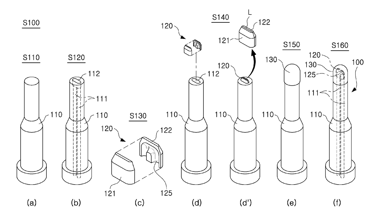
[0047]As set forth above, according to embodiments of the present invention, the internal space (the first space) of the body part is formed through simple machining such as drilling, a complex-shaped internal space (the second space) is separately fabricated as the space formation member, and the finishing part forms the exterior of the metal product by covering the first space and the second space, whereby an internal space having a complex configuration can be easily obtained. In particular, according to embodiments of the present invention, the rectilinear portion of the body part forming the first space is formed by drilling, the second space including the curved portion is formed by a conventional manufacturing process (for example, cutting, casting, or the like), AF processing (DMF processing, multilayer laser cladding processing, or the like), or any combination of processing processes thereof, and the first space and the second space are coupled to be thereby allow for easy formation of the internal space having a complex configuration. Therefore, according to embodiments of the present invention, time and costs required for manufacturing the metal product (a mold) can be reduced.
[0048]According to embodiments of the present invention, since the cross-sectional dimension of the internal space is made uniform and the direction of a coolant is smoothly altered along a curved surface of the internal space in a state in which turbulence or congestion is not generated in the coolant flow, and therefore cooling efficiency of the metal product can be improved. In particular, an internal space (a cooling channel) having a complex configuration can be formed so as to allow for a uniform temperature at the surface of the metal product. Through this, improvements in the performance of a finished product manufactured using the metal product can be expected.
[0049]According to embodiments of the present invention, since the internal space (a cooling channel), the direct fabrication of which is difficult only through the DMF or multilayer laser cladding technique according to the related art, can be fabricated as the space formation member, the internal space having a complex configuration (for example, a curvature portion and / or an overhang structure) can be fabricated without complex controlling of 5-axis equipment.
[0050]In addition, in the case of using additional metal powder having a low-melting point according to the related art, the surface of the internal space (a cooling channel) is rather rough, and corrosion (in particular, galvanic corrosion) in the cooling channel occurs in the event of the metal with a low-melting point remaining in the cooling channel without being completely removed. However, according to embodiments of the present invention, the surface of the channel is smooth to thereby allow for low passage resistance and less corrosion.
[0051]In addition, in the case of forming the internal space (a cooling channel) by using a copper tube according to the related art, there are disadvantages, such as uneven cross-sections at bent portions of the copper tube. Further, according to the related art, only approximately a half of the cross-sectional area of the copper tube is coupled to the body part, whereby cooling efficiency is rather reduced. However, according to embodiments of the present invention, since the cross-section of the internal space is uniform and the direction of a coolant is smoothly altered along the curved surface of the internal space, turbulence or congestion is not generated in the coolant flow. In addition, according to embodiments of the present invention, the majority of the surface of the space formation member is entirely metallically bonded to the body part or the finishing part to thereby allow for superior cooling efficiency. Furthermore, according to embodiments of the present invention, a 3D internal space can be efficiently fabricated by using a plurality of space formation members.
[0052]Further, according to embodiments of the present invention, the space formation member is stably mounted in the mounting groove, whereby metallic bonding between the space formation member and the finishing part and / or the body part can be stably undertaken at the time of performing AF processing, such as subsequent DMF or multilayer laser cladding processes.

Problems solved by technology

In plastic injection molding, the high surface temperature of the mold extends the cycle time to manufacture a plastic product, and the non-uniform temperature distribution at the surface of the mold induces various defects in products such as warpage, thickness variation, and / or a large amount of micro-pores.
However, cooling channel (line) fabrication has been confined to relatively simple configurations, such as straight cooling channel fabricated by gun-drilling, baffle cooling channels, and the like, primarily due to the limits of the conventional metal fabrication methods (including cutting, casting, electrical discharge machining, etc.) used to manufacture the mold and the industrial metal product.
Practically, the mold and the metal product with complicated and / or curved cooling channel cannot be made by using the conventional metal fabrication methods because freely manufacturing the configuration and the geometry of the cooling channel is impossible by using the only combination of the straight and the baffle cooling channel made by the conventional metal fabrication methods.
In addition, since the fabrication of the straight cooling channel and the baffle cooling channel does not allow for the formation of a curved channel in which the direction of a coolant is smoothly altered at a turning portion, turbulence or congestion is generated in the coolant flow at a drilling-overlap portion and / or a portion provided with a baffle to thereby lead to extremely low cooling efficiency.
However, the SLS and the SLM techniques have limitations in that a great deal of mold manufacturing costs is incurred due to the use of a relatively expensive special metal powder, water leakage may occur in a manufactured cooling channel due to defects, such as cracks, pores, or the like, a corrosion rate is relatively rapid due to the rough surface of the manufactured cooling channel, a clogging phenomenon has been often reported in the cooling channel, the size of a manufactured product is limited, or the like.
Thus, these techniques have not been widely industrially employed in manufacturing the three-dimensional cooling channel in practice.
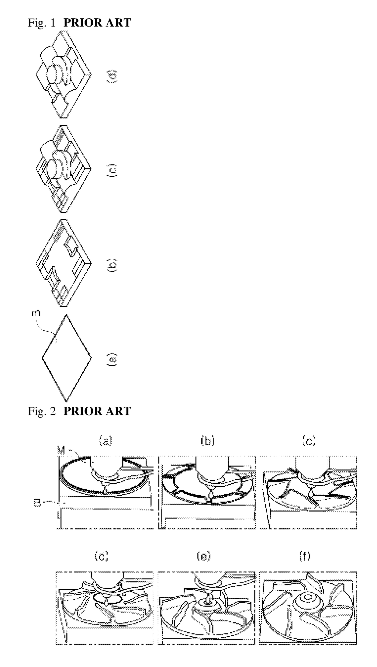
However, since the DMF and multilayer laser cladding techniques do not include metal powder (or a metal powder layer) acting as a support, unlike the SLS or SLM technique, the manufacturing of an overhang structure having an empty space formed in the lower side thereof is not facilitated.
Accordingly, in order to form the overhang structure (including a cooling channel having the overhang structure) through the DMF and multilayer laser cladding techniques, controlling complex motions of relatively expensive 5-axis equipment is generally required.
In this case, there are limitations in that an additional process for manufacturing the cooling channel is required, the surface of the cooling channel can be rather rough, and corrosion (in particular, galvanic corrosion) in the cooling channel can occurs due to metal having a low melting point remaining in the cooling channel without being completely removed.
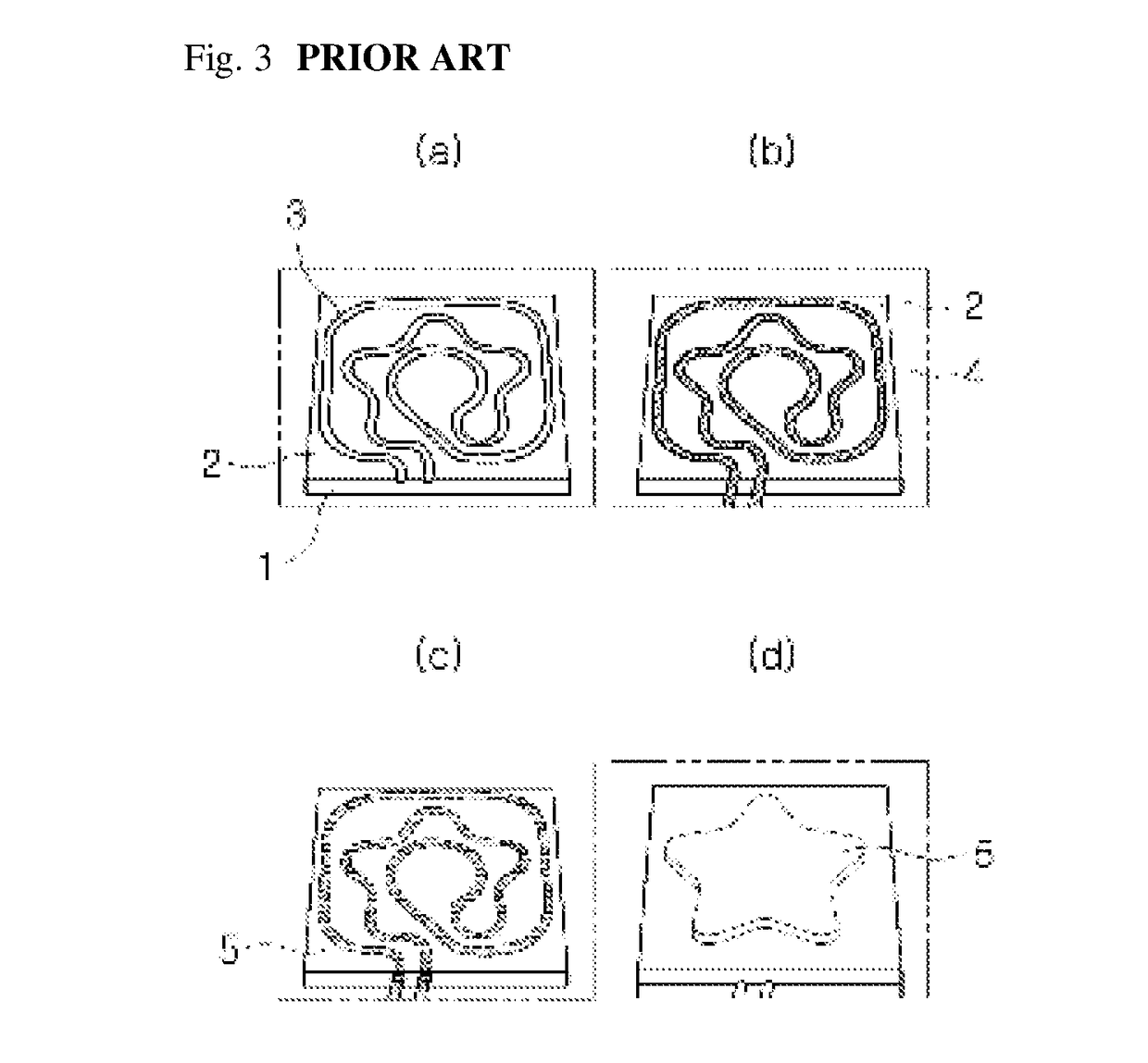
The method of inserting the copper tube illustrated in FIGS. 3A through 3D has advantages, such as simplicity of manufacturing, smooth surfaces, and high corrosion resistance in the cooling channel; however, it has also disadvantages, such as a reduction in cooling efficiency, because an upper portion of the inserted copper tube 4 forms a complete metallic bond with the metal layers 5 (or the metal product) deposited on it, while a lower portion of the copper tube 4 installed in the mounting groove 3 is separated from the metal product and is not bonded thereto.
In particular, in the case of sharply bending the copper tube 4 in order to form a complex and curved cooling channel, uneven cross-sections in bent portions of the copper tube 4 can be formed, resulting in the occurrence of turbulence in a coolant flow within the copper tube in the event of excessive bending of the copper tube.
In this manner, in the case of the occurrence of the lifting phenomenon, there are many difficulties in manufacturing an upper portion of a final metal product on the copper tube 4 through the DMF and multilayer laser cladding techniques.
That is, while the DMF and multilayer laser cladding techniques allow for the deposition of a metal layer corresponding to a 2D cross-section along a path calculated from 3D CAD data, the configuration of the path calculated from 3D CAD data and the actual configuration of the copper tube 4 are different at the location of the occurrence of the lifting phenomenon to thereby cause difficulties in the attainment of a perfect molding.

Method used


Image

  • Metal product having internal space formed therein and method of manufacturing thereof
  • Metal product having internal space formed therein and method of manufacturing thereof
  • Metal product having internal space formed therein and method of manufacturing thereof

Examples


Embodiment Construction

[0064]Terms used in the specification are merely used for the explanation of specific embodiments according to the present invention, and are not intended to limit the scope of the present invention. In addition, a singular expression may include a plural expression in the specification.

[0065]Hereinafter, embodiments of the present invention will now be described in detail with reference to the accompanying drawings.

[0066]FIGS. 4A through 4F are schematic perspective views sequentially illustrating a process of manufacturing a metal product according to an embodiment of the present invention. FIGS. 5A and 5B are views illustrating various embodiments of the metal product according to the present invention, each having a front view and a cross-sectional view. FIGS. 6A, 6B, and 6C are respectively, a plan view, a cross-sectional view, and a front view illustrating another embodiment of the metal product according to the present invention. FIGS. 7A and 7B are views illustrating another...


PUM

PropertyMeasurementUnit
volumeaaaaaaaaaa
surface temperatureaaaaaaaaaa
temperatureaaaaaaaaaa

Abstract

There are provided a metal product having an internal space formed therein, allowing for improvements in the flow of a coolant in the internal space, such as a cooling channel and an increase in cooling efficiency, and a method of manufacturing thereof. The metal product includes a body part having a first space formed therein; a space formation member having a second space formed therein, mounted on the body part to be communicated with the first space; and a finishing part forming an exterior by covering the space formation member in a state in which the space formation member is mounted on the body part.

Description

TECHNICAL FIELD[0001]The present invention relates to a metal product having an internal space formed therein and a method of manufacturing thereof, and more particularly, to a metal product in which an internal space having complicated configuration and geometry is easily formed, and a method of manufacturing thereof. In particular, the present invention relates to a metal product having an internal space formed therein, allowing for improvements in the flow of a coolant (cooling water) in the internal space, such as a cooling channel and an increase in cooling efficiency, and a method of manufacturing thereof. The metal product includes a mold having a cooling channel, and a variety of industrial metal products requiring surface and / or volume cooling (for example, a machine tool and a device having a cooling channel, or the like).BACKGROUND ART[0002]The cooling of a mold and a metal product to reduce a surface temperature and / or to obtain the uniform temperature distribution at th...

Claims


Application Information

Patent Timeline
Patent Type & Authority Patents(United States)
IPC IPC(8): B23P17/00B23P15/00B21D37/20B22F5/10B29C45/73B22F3/00B22F3/105
CPCB23P17/00B21D37/20B22F3/008B22F3/1055B22F5/10B23P15/007B29C45/7312Y02P10/295Y10T29/49826Y10T428/12B33Y10/00B33Y80/00Y02P10/25B22F10/28B22F12/20B22F10/25B22F10/385B22F7/00B23P15/24B23P23/04B29C33/3842
Inventor SUH, JEONG-HUN
Owner INSSTEK
Learn More