Method of reducing downward flow of air currents on the lee side of exterior structures

a technology of air currents and exterior structures, which is applied in the field of reducing the downward flow of air currents on the lee side of exterior structures, can solve the problems of dangerously unsafe driving conditions, other undesired negative effects, and reducing the visibility of neighboring properties, so as to reduce prevent or lessen the effect of emissions and reducing the downward flow of air currents

Inactive Publication Date: 2015-03-17
ZEELAND WOOD TURNING WORKS
View PDF6 Cites 0 Cited by
  • Summary
  • Abstract
  • Description
  • Claims
  • Application Information

AI Technical Summary

Benefits of technology

[0003]An embodiment of the present disclosure is directed to a method of reducing the downward flow of air currents on the leeward side of an emissions emitting structure comprising the step of using a system that includes components chosen from the group consisting of one or more mechanical air moving devices; physical structures; and combinations thereof to create an increase in the air pressure within a volume of air on the leeward side of an emissions emitting structure having emissions that become airborne. The increased air pressure prevents or lessens downward flow of emissions that would occur without the use of the system.
[0004]Yet another aspect of the present disclosure is directed to a method of reducing the downward flow of air currents on the leeward side of an emissions emitting structure comprising the steps of (1) installing components outside and proximate the emissions emitting structure wherein the components are chosen from the group consisting of one or more industrial fans; one or more vertically or substantially vertically oriented walls that are at least 20% of the height of a tallest exterior wall on the leeward side of the emissions emitting structure; and (2) creating an increase in the air pressure within a volume of air proximate and along the leeward side of an emissions emitting structure using the components to cause at least two airflows to meet one another and create the increase in the air pressure that reduces the downward flow of air currents on the leeward side of the emissions emitting structure.
[0005]Another aspect of the present disclosure is generally directed to a method of reducing the downward flow of air currents on the leeward side of an emissions generating building and preventing emissions from lessening or blocking the visibility of a motorist traveling a road near the building comprising the step of: creating an increased air pressure zone proximate the leeward side of the building by using at least one airflow creating system that includes components chosen from the group consisting of two or more mechanical air moving devices; physical airflow directing structures; and combinations thereof to create at least two airflows that meet proximate, more typically along, the leeward side of the emission generating building and increase the air pressure within the zone of air on the leeward side of an emissions generating building chosen from the group consisting of a factory having emissions that become airborne, a power plant having emissions that become airborne, and an industrial or commercial facility having emissions that become airborne; wherein the increased air pressure zone prevents or lessens downward flow of emissions that would occur without the use of the system and presents the emissions from lessening or blocking the visibility of the motorist traveling the road.

Problems solved by technology

This reduces visibility on such neighboring properties and / or causes other undesired negative effects.
Some undesired effects include causing dangerously unsafe driving conditions by reducing visibilities along affected stretches of roadways (see FIG. 1, for example).

Method used


Image

  • Method of reducing downward flow of air currents on the lee side of exterior structures
  • Method of reducing downward flow of air currents on the lee side of exterior structures
  • Method of reducing downward flow of air currents on the lee side of exterior structures

Examples


Embodiment Construction

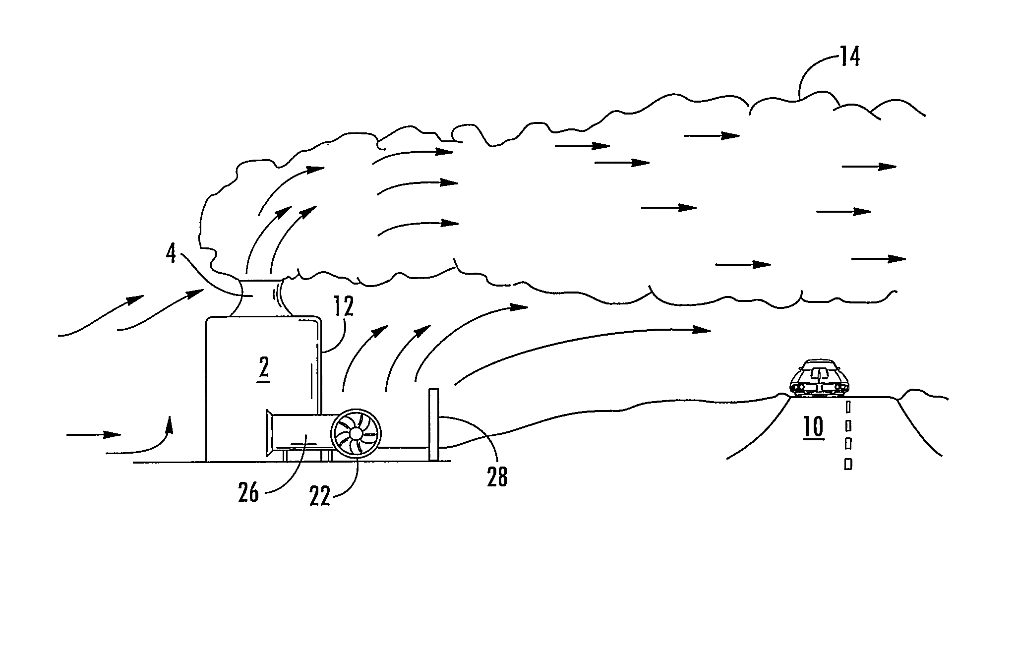
[0011]For purposes of description herein, the terms “upper,”“lower,”“right,”“left,”“rear,”“front,”“vertical,”“horizontal,” and derivatives thereof shall relate to the invention. However, it is to be understood that the invention may assume various alternative orientations, except where expressly specified to the contrary. It is also to be understood that the specific devices and processes illustrated in the attached drawings, and described in the following specification are simply exemplary embodiments of the inventive concepts defined in the appended claims. Hence, specific dimensions and other physical characteristics relating to the embodiments disclosed herein are not to be considered as limiting, unless the claims expressly state otherwise.

[0012]Where a range of values is provided, it is understood that each intervening value, to the tenth of the unit of the lower limit unless the context clearly dictates otherwise, between the upper and lower limit of that range, and any other...


PUM

PropertyMeasurementUnit
angleaaaaaaaaaa
angleaaaaaaaaaa
angleaaaaaaaaaa

Abstract

A method of reducing the downward flow of air currents on the leeward side of an emissions emitting structure including the step of using a system that includes components chosen from the group consisting of one or more mechanical air moving devices; physical structures; and combinations thereof to create an increase in the air pressure within a volume of air on the leeward side of an emissions emitting structure having emissions that become airborne. The increased air pressure prevents or lessens downward flow of emissions that would occur without the use of the system and increases the safety by which one can travel a road or other transportation route that might otherwise be visually obscured by the emissions and the safety of the property and those within the area where emissions occur.

Description

CROSS-REFERENCE TO RELATED APPLICATION[0001]This application claims priority to U.S. Provisional Patent Application Ser. No. 61 / 544,064, filed on Oct. 6, 2011, entitled METHOD OF REDUCING DOWNWARD FLOW OF AIR CURRENTS ON THE LEE SIDE OF EXTERIOR STRUCTURES, the entire disclosure of which is hereby incorporated by reference in its entirety.BACKGROUND OF THE INVENTION[0002]As shown in FIGS. 1-2, emissions emitting building structures 2, typically industrial factories or utility generating structures, often utilize an emission tower or towers, such as a steam tower (steam emitting cooling tower), cooling tower, or smokestack. The emission tower is typically located on a roof 6 or other elevated surface of the emissions emitting structure. When directional winds / air currents 8 flow past an exterior structure, such as an emission emitting structure (steam) tower containing facility, toward neighboring properties including roads 10, the base structure itself can cause or contribute to emi...

Claims


Application Information

Patent Timeline
Patent Type & Authority Patents(United States)
IPC IPC(8): F17D1/16
CPCE01F7/00E04H5/12Y10T137/0391
Inventor BOONSTRA, KEITH ERWIN
Owner ZEELAND WOOD TURNING WORKS
Why Eureka
Try Eureka