Sliding sleeve bypass valve for well treatment

a technology of sliding sleeve and bypass valve, which is applied in the direction of sealing/packing, drilling machines and methods, and wellbore/well accessories, etc., can solve the problems of limited number of balls that can be run in a single tubing string, and achieve the effect of reducing the risk of accidental sleeve actuation, avoiding accidental shifting or “skipping” of sleeve positions, and avoiding accidental sleeve actuation

Inactive Publication Date: 2015-03-17
HALLIBURTON ENERGY SERVICES INC
View PDF8 Cites 29 Cited by
  • Summary
  • Abstract
  • Description
  • Claims
  • Application Information

AI Technical Summary

Benefits of technology

[0006]The disclosed downhole bypass valve utilizes a stationary sleeve defining an interior ball-seat. When a dropped ball is seated, fluid differential pressure is diverted to an annular area adjacent a first sliding sleeve. The sleeve slides in response to the pressure differential upon shearing of a shear pin, or similar, and opens ports to the wellbore annulus. Treatment or maintenance operations can then occur through the ports, which can be fitted with nozzles. A second sliding sleeve, independent from the first, is operated in response to dropping a second ball into the device. The second ball diverts fluid differential pressure to an annular area adjacent the second sleeve and movement occurs when a shear pin shears. The second sleeve covers the ports to the wellbore annulus and closes the valve. After a sliding sleeve shifts, pressure across the sleeve is equalized, allowing reverse flow without risk of accidental sleeve actuation. Accidental shifting or “skipping” of sleeve positions is reduced as the sleeves are independently operated.

Problems solved by technology

Despite the general effectiveness of such assemblies, practical limitations restrict the number of balls that can be run in a single tubing string.
Further, staged sliding sleeves can tend to “skip” positions in response to raised tubing pressure, creating issues with opening a zone to treatment, etc.

Method used


Image

  • Sliding sleeve bypass valve for well treatment
  • Sliding sleeve bypass valve for well treatment
  • Sliding sleeve bypass valve for well treatment

Examples


Embodiment Construction

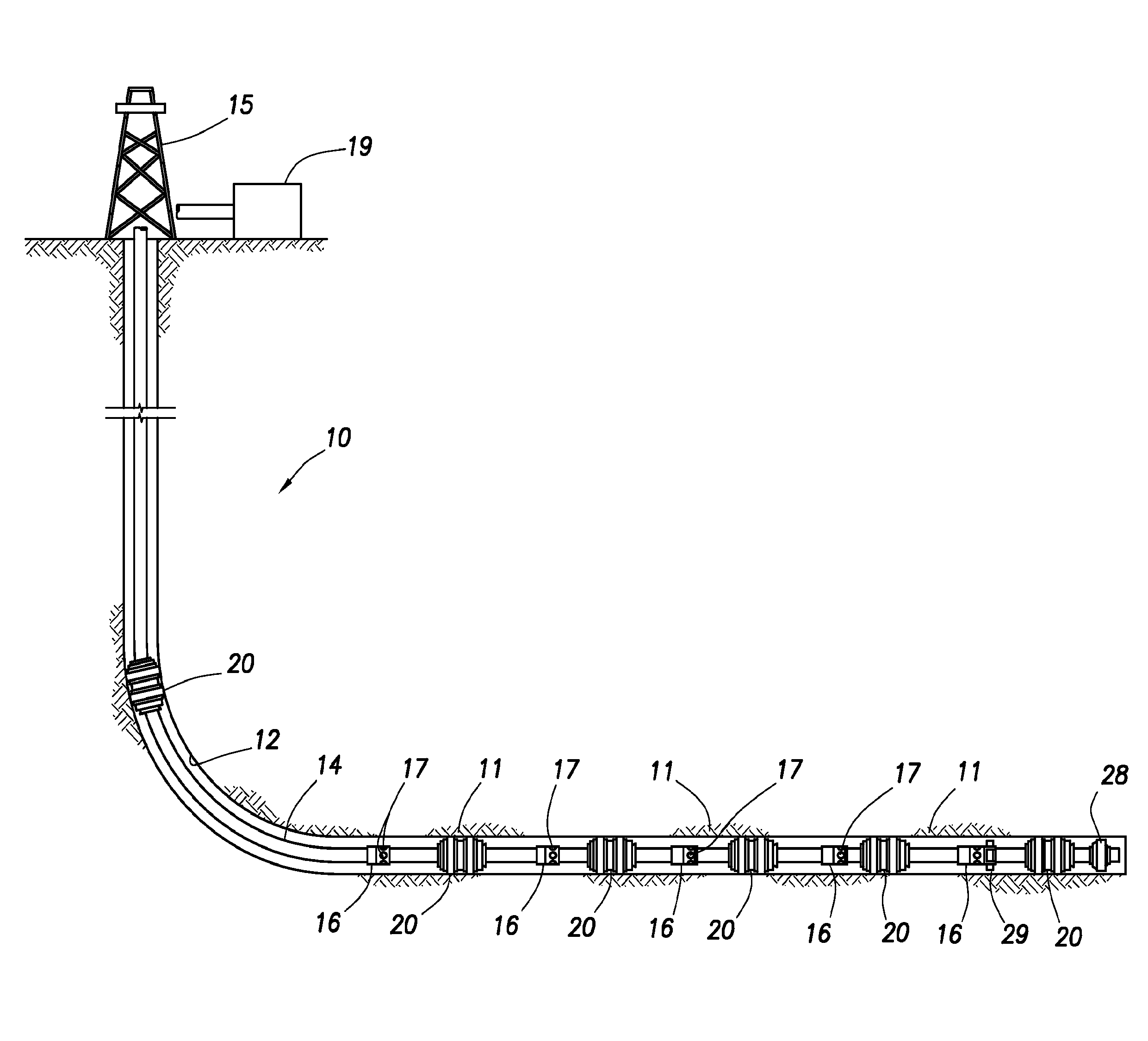
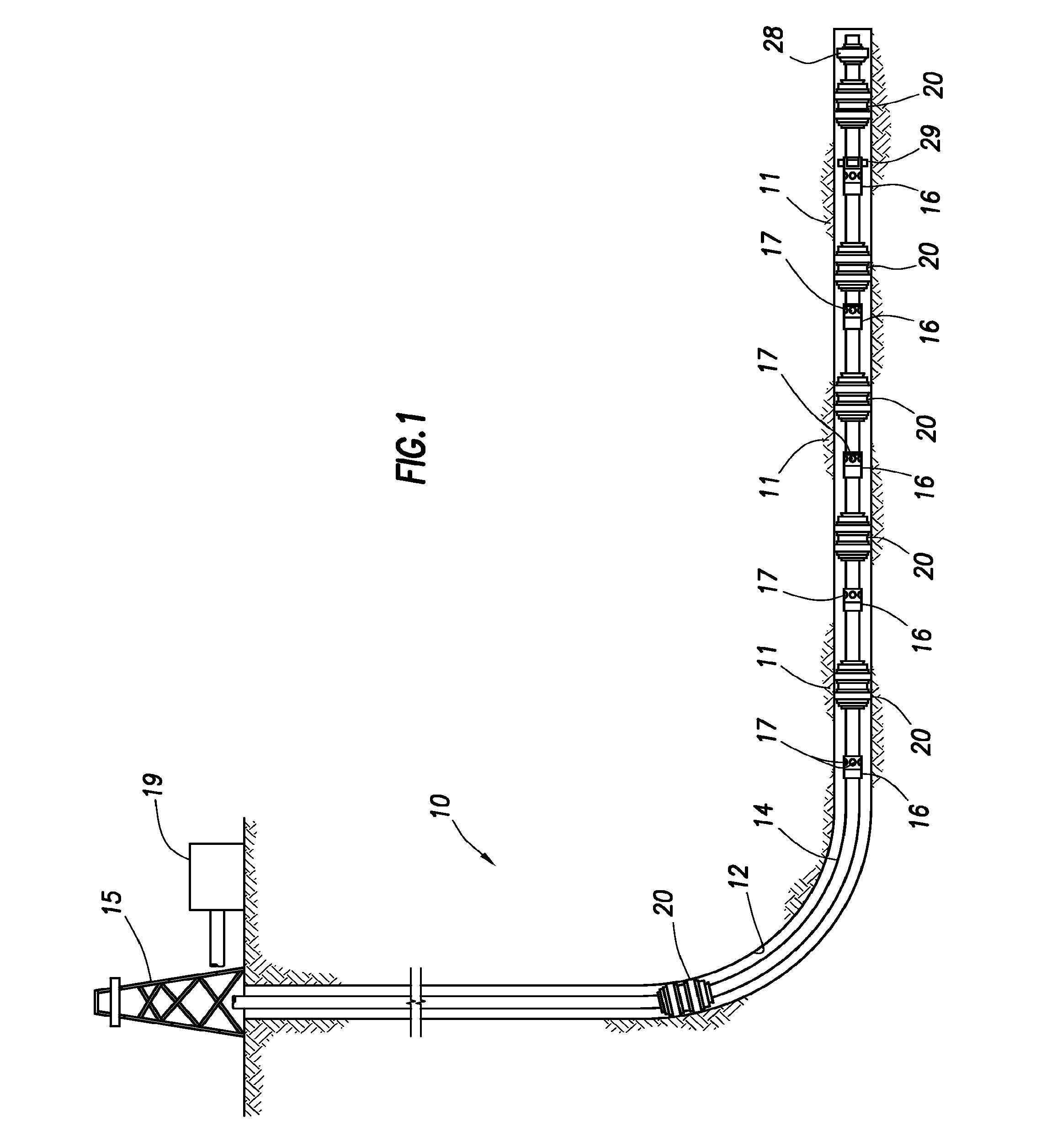
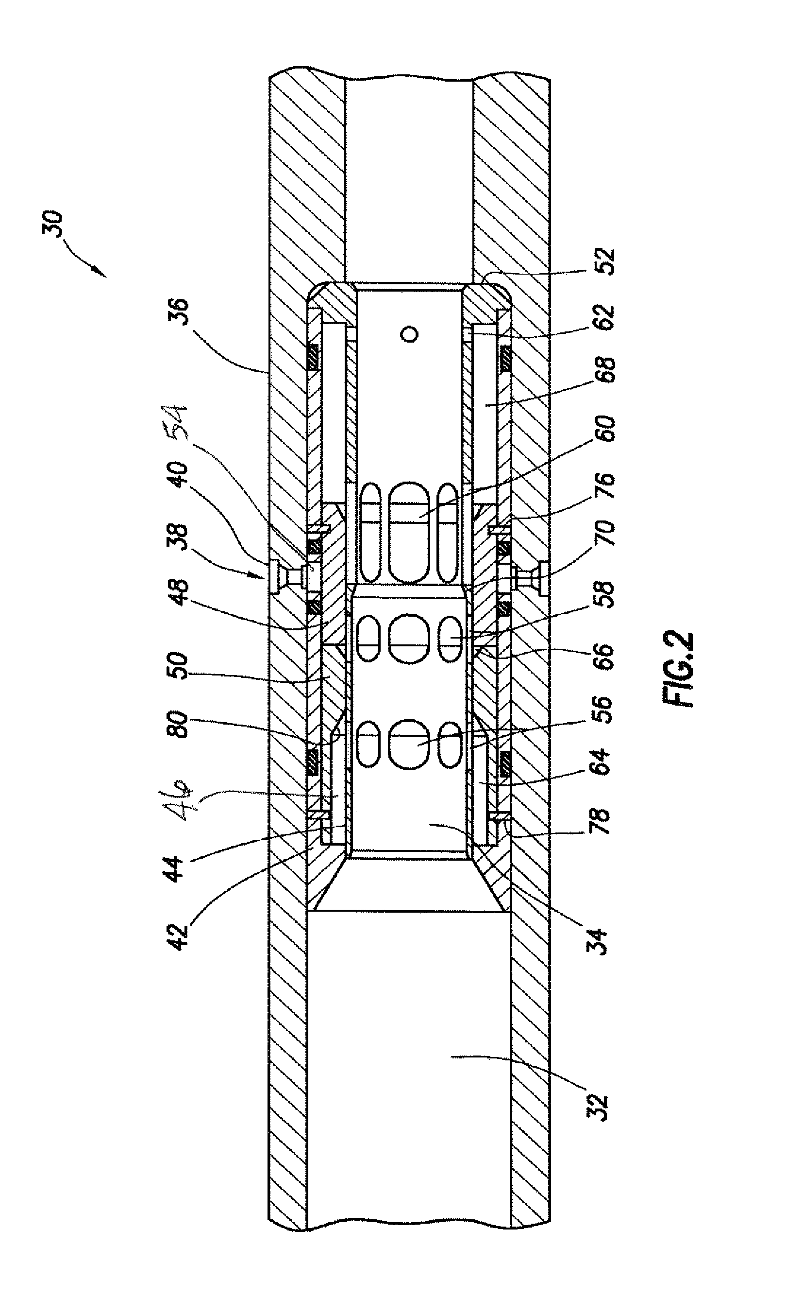
[0014]While the making and using of various embodiments of the present invention are discussed in detail below, a practitioner of the art will appreciate that the present invention provides applicable inventive concepts which can be embodied in a variety of specific contexts. The specific embodiments discussed herein are illustrative of specific ways to make and use the invention and do not limit the scope of the present invention. The description is provided with reference to a horizontal wellbore. However, the inventions disclosed herein can be used in horizontal, vertical, or deviated wellbores. As used herein, the words “comprise,”“have,”“include,” and all grammatical variations thereof are each intended to have an open, non-limiting meaning that does not exclude additional elements or steps. The terms “uphole,”“downhole,” and the like, refer to movement or direction closer and farther, respectively, from the wellhead, irrespective of whether used in reference to a vertical, hor...


PUM


Abstract

A downhole bypass valve utilizes a stationary sleeve defining an interior ball-seat. When a dropped ball is seated, fluid differential pressure is diverted to an annular area adjacent a first sliding sleeve. The sleeve slides in response to the pressure differential upon shearing of a shear pin, or similar, and opens ports to the wellbore annulus. Treatment or maintenance operations can then occur through the ports, which can be fitted with nozzles. A second sliding sleeve, independent from the first, is operated in response to dropping a second ball into the device. The second ball diverts fluid differential pressure to an annular area adjacent the second sleeve and movement occurs when a shear pin shears. The second sleeve covers the ports to the wellbore annulus and closes the valve. After a sliding sleeve shifts, pressure across the sleeve is equalized, allowing reverse flow without risk of accidental sleeve actuation.

Description

CROSS-REFERENCE TO RELATED APPLICATIONS[0001]None.FIELD OF INVENTION[0002]Methods and apparatus are presented for selective treatment of a wellbore or formation. More specifically, the inventions relate to methods and apparatus for selective fluid communication between a work string and wellbore utilizing a sliding-sleeve, bypass valve device.BACKGROUND OF INVENTION[0003]The present inventions relate, generally, to apparatus and methods used in well servicing and treatment operations. More specifically, these inventions relate to downhole apparatus used to selectively provide a flow passage from a tubular string into the wellbore annulus between the tubular string and the casing (or open hole) in which it is run.[0004]As is common in the art, nozzles or ports can be utilized to inject fluid into the annulus surrounding a tubing string to clean various components in the wellbore. For example, cleaning of subsea surfaces and profiles of subsea wellheads, blowout preventers (BOPs) and ...

Claims


Application Information

Patent Timeline
Patent Type & Authority Patents(United States)
IPC IPC(8): E21B34/14E21B23/04E21B34/00E21B43/14
CPCE21B34/14E21B43/14E21B23/04E21B2034/007E21B2200/06E21B34/142
Inventor TILLEY, DAVID J
Owner HALLIBURTON ENERGY SERVICES INC
Why Eureka
Try Eureka