Cushion clip

a technology of cushion and clip, applied in the field of cushion clips, can solve problems such as noise generation, and achieve the effect of dampening collisions

Active Publication Date: 2015-03-24
DAIWA KASEI IND CO LTD
View PDF8 Cites 9 Cited by
  • Summary
  • Abstract
  • Description
  • Claims
  • Application Information

AI Technical Summary

Benefits of technology

[0006]For example, one aspect of the present invention may provide a cushion clip that is configured to be attached to a first member of two members capable of relatively moving toward each other in order to dampen collision between the two members, which may include a support portion made of a hard material and capable of being connected to an attachment hole formed in the first member, and a cushioning portion made of a soft material and integrally connected to the support member by two-color molding. The support portion is integrally formed and has an engagement portion that is configured to be inserted into and engaged with the attachment hole, and a head portion to which the cushioning portion is integrally connected by two-color molding. The head portion has a shoulder surface that is formed in a columnar portion thereof. The shoulder surface is directed in an insertion direction of the support portion into the attachment hole. The cushioning portion is configured to project from the first member when the support portion is connected to the attachment hole, so as to elastically absorb impact from a second member. The cushioning portion has a base portion that is positioned to surround the columnar portion of the head portion. The base portion of the cushioning portion has a bulged portion that is formed in at least a portion thereof so as to extend along the columnar portion. The bulged portion is shaped to project beyond the shoulder surface in the insertion direction of the support portion, so as to elastically contact the first member when the cushion clip is applied with the impact from the second member.
[0007]According to the aspect of the invention, when the cushion clip is applied with the impact from the second member, the cushioning portion is capable of elastically receiving and absorbing the impact. At this time, the bulged portion of the cushioning portion may elastically contact the first member while the support portion cannot contact the first member. As a result, production of noise can be eliminated.
[0008]Optionally, the head portion may include an enlarged portion. The enlarged portion of the head portion may be configured to support the base portion of the cushioning portion when the impact is applied to the cushion clip from the second member, so as to prevent the base portion from excessively deforming in a direction opposite to the insertion direction of the support portion.

Problems solved by technology

However, in the known cushion clip 101, when the cushion clip 101 is pressed by the door D2 due to vibration caused by traveling of the vehicle, the engagement portion 110 made of the hard resinous material can contact the door frame F2, thereby generating noise.

Method used


Image

  • Cushion clip
  • Cushion clip
  • Cushion clip

Examples


Embodiment Construction

[0020]Next, a representative embodiment of the present invention will be described with reference to FIGS. 1 to 9.

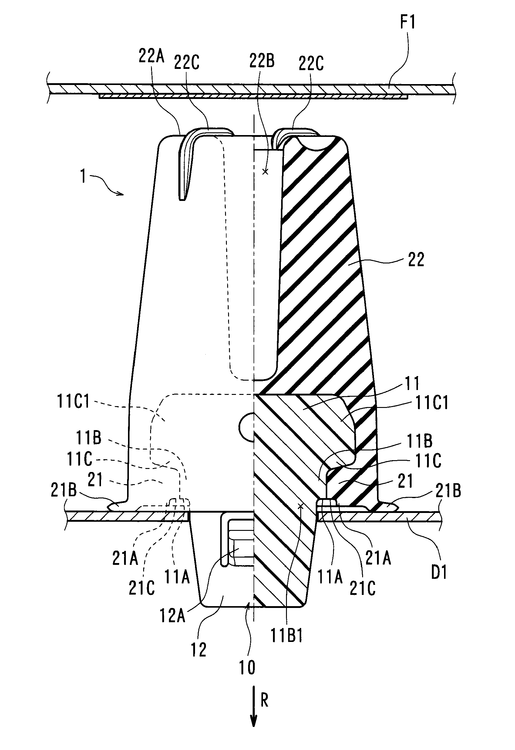
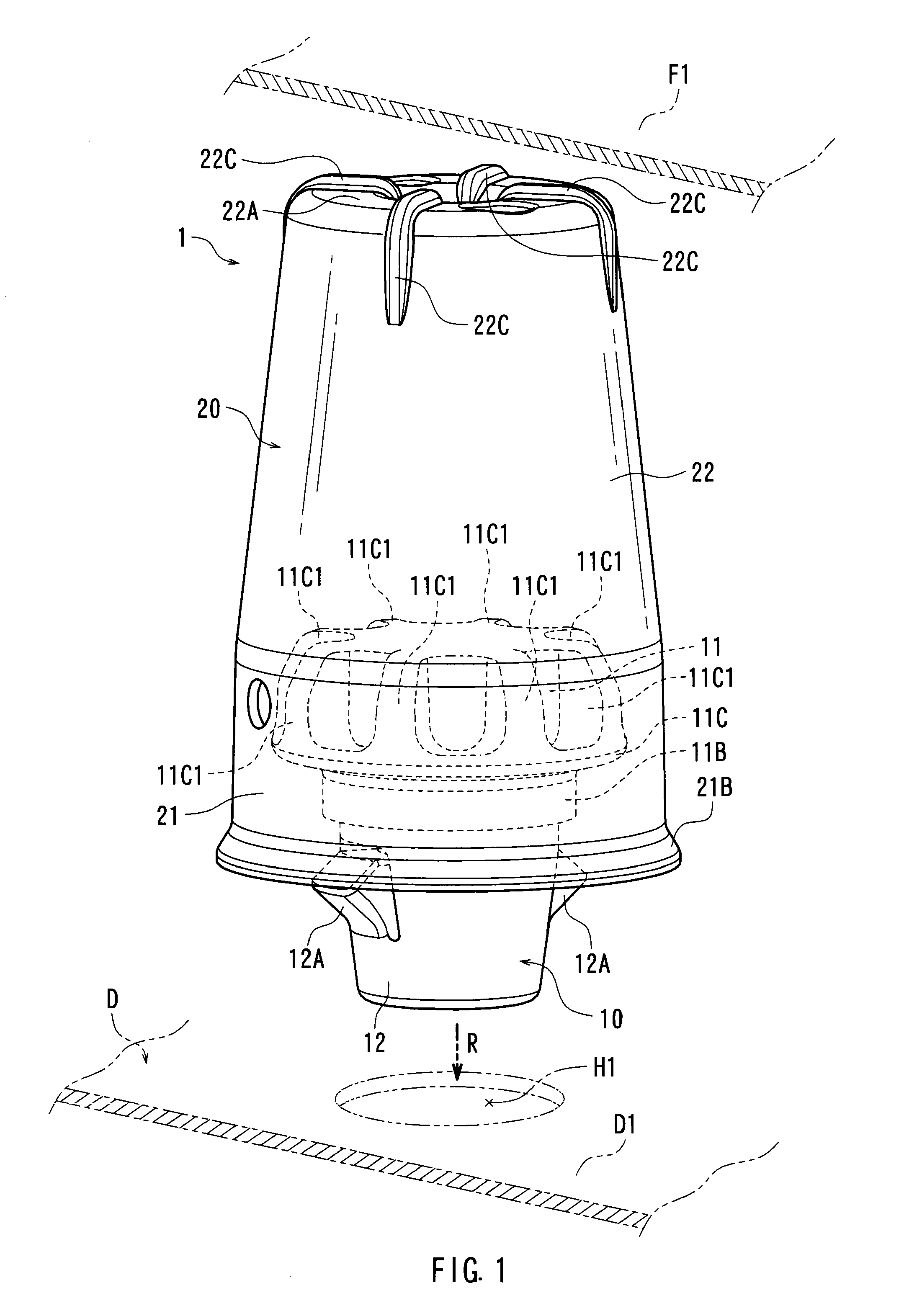
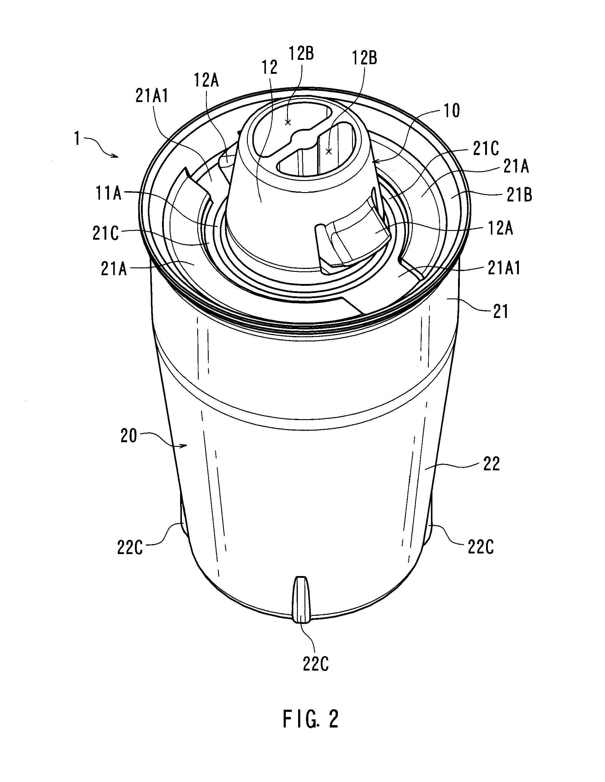
[0021]As shown in FIGS. 1 and 7, a representative cushion clip 1 may be configured to be attached to a back door D (a first or attachment member) of a vehicle (not shown), so as to dampen collision between the door D and a body panel F1 (a second or associated member) when the door D is closed and to absorb impact produced therebetween. The cushion clip 1 may preferably be integrally formed. The cushion clip 1 may include a support (hard) portion 10 that is constructed to be connected to an (circular) attachment hole H1 formed in a door panel D1 of the door D, and a cushioning portion 20 that is constructed to be projected from the door panel D1 to elastically receive and absorb the impact produced between the door D and the body panel F1 when the door D is closed.

[0022]The support portion 10 may preferably be made of a hard resinous material having rigidity such as poly...


PUM

PropertyMeasurementUnit
circumferenceaaaaaaaaaa
heightaaaaaaaaaa

Abstract

A cushion clip may include a support portion capable of being connected to an attachment hole formed in a first member and a cushioning portion integrally connected to the support member. The support portion has an engagement portion and a head portion. The head portion has a shoulder surface that is formed in a columnar portion thereof. The cushioning portion has a base portion that is positioned to surround the head portion. The base portion of the cushioning portion has a bulged portion that is formed therein. The bulged portion is shaped to project beyond the shoulder surface in an insertion direction of the support portion, so as to elastically contact the first member when the cushion clip is applied with the impact from a second member.

Description

BACKGROUND OF THE INVENTION[0001]1. Field of the Invention[0002]The present invention relates to a cushion clip. More particularly, the present invention relates to a cushion clip that is attached to one (i.e., an attachment member) of two members capable of relatively moving toward each other in order to dampen collision between the two members and to absorb impact from the other of the two members.[0003]2. Description of Related Art[0004]A known cushion clip of this type is taught by, for example, Japanese Patent Number 3401242. As shown in FIG. 10, a cushion clip 101 is attached to a door frame F2 (an attachment member) of a vehicle, so as to dampen collision between the door frame F2 and a door D2 (an associated member) when the door D2 is closed. The cushion clip 101 may be integrally formed. The cushion clip 101 may include an engagement portion 110 that is capable of being inserted into an attachment hole H2 formed in the door frame F2, and a cushioning portion 120 that is co...

Claims


Application Information

Patent Timeline
Patent Type & Authority Patents(United States)
IPC IPC(8): E05F5/00E05F5/02
CPCE05F5/022E05F5/025Y10T24/4588Y10T24/44026F16F7/00F16F7/12F16B19/00B29C45/16
Inventor KAJI, ATSUTOSHIKATO, MAKOTO
Owner DAIWA KASEI IND CO LTD
Why Eureka
Try Eureka