Chain drive device

一种链传动、滚子链的技术,应用在链传动装置领域,能够解决滚子、联结销耐久性降低等问题

Inactive Publication Date: 2013-04-24
TSUBAKIMOTO CHAIN CO
View PDF10 Cites 6 Cited by
  • Summary
  • Abstract
  • Description
  • Claims
  • Application Information

AI Technical Summary

Problems solved by technology

[0007] In the bushless roller chain, unlike the roller chain in which there is a bush fixed on the inner link plate between the roller and the coupling pin, since the roller and the coupling pin directly support the roller rotatably Therefore, when the rollers and the sprocket teeth start to mesh, there is a problem that a large impact force acts on the rollers and the coupling pins, which reduces the durability of the rollers and the coupling pins.

Method used


Image

  • Chain drive device
  • Chain drive device
  • Chain drive device

Examples


Embodiment Construction

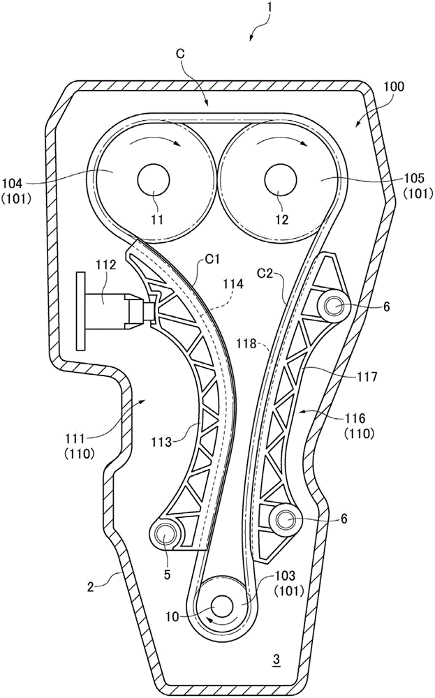
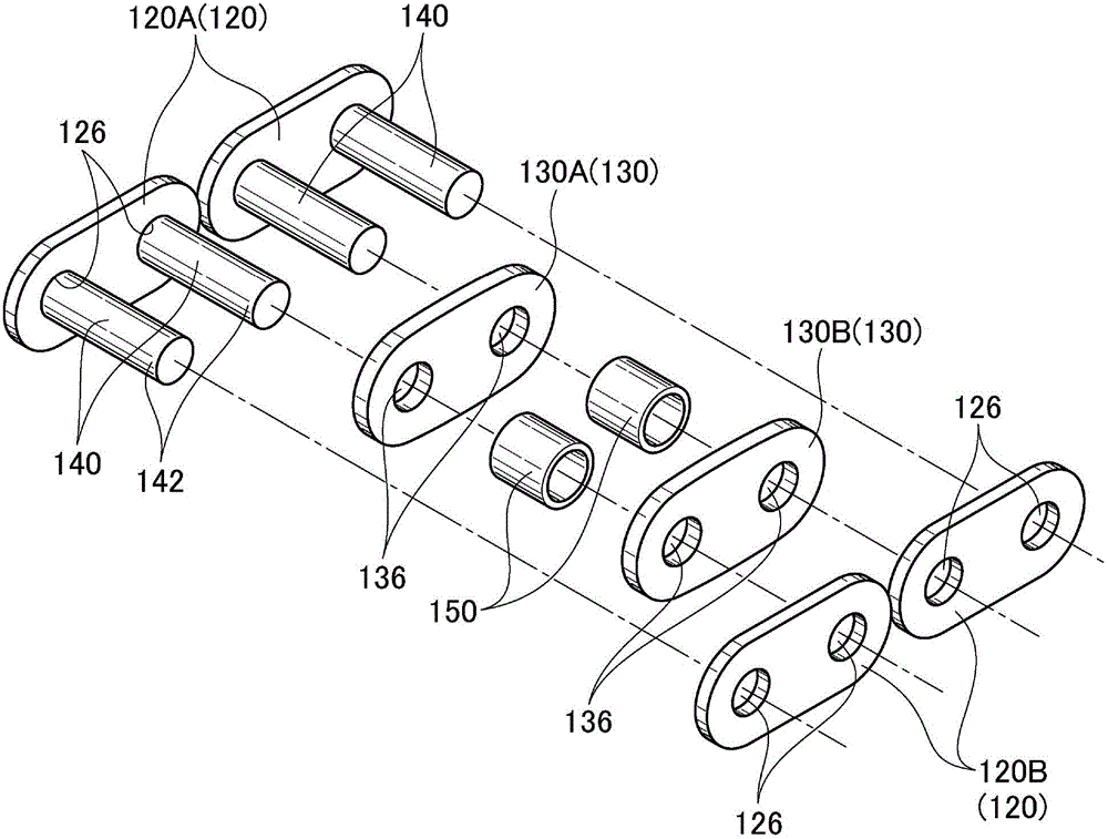
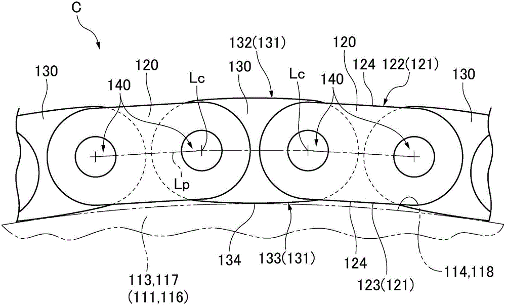
[0053] The chain transmission device of the present invention has a bushless roller chain, a plurality of sprockets, and a chain guide. In the bushless roller chain, a pair of outer link plates and a pair of outer link plates arranged between the pair of outer link plates The inner chain plates are connected by connecting pins that directly support a pair of inner chain plates rotatably and directly support rollers disposed between the pair of inner chain plates, and are alternately linked along the chain travel direction; The sprocket has a plurality of sprocket teeth capable of engaging each roller; the chain guide has a sliding contact for the advancing bushless roller chain while guiding the bushless roller chain in the direction of chain travel On the surface, the bushless roller chain is lubricated by lubricating oil, and the coupling pin is set on the outer chain plate so that it cannot move relatively, and is inserted into the through hole set on the inner chain plate, ...


PUM


Abstract

The invention provides a chain drive device which can improve the transmission efficiency of a non-lining roller chain and improve the durability of an inner plate and a joint pin at the same time, alleviates the impact when a roller and a sprocket begin to engage with each other, reduces noise, and improves the durability of the roller and the joint pin. In the non-lining roller chain (C) of the chain drive device, the joint pin (140) which cannot move relatively to an outer plate (120) is embedded in a via hole (136) in the inner plate (130). An oil film having lubricating oil is formed between the joint pin (140) and the roller which can be rotatably directly supported by the joint pin (140). In the chain (C), only the inner plate (130) is in sliding contact with sliding contact surfaces (114, 118) of a chain guiding device through a back surface (133) of the inner plate (130). The back surface (133) has an arc contact part (134) formed in a chain-heading direction.

Description

technical field [0001] The present invention relates to a chain transmission having a bushless roller chain having rollers supported directly by coupling pins connecting outer and inner link plates. Also, the chain transmission is used in automobiles, industrial machines, transport machines, and the like. Background technique [0002] There is known a chain drive with a bushless roller chain and a sprocket, in which the outer link plate and the inner link plate rotatably support the inner link plate directly and through the rotatable support The rollers are linked by coupling pins and are alternately linked in the chain travel direction; the sprocket has a plurality of sprocket teeth capable of meshing with the rollers (for example, see Patent Documents 1 and 2). [0003] There is known a chain transmission having a bushless roller chain and a sprocket, in which a pair of outer link plates and a pair of inner link plates are rotatably directly supported by a pair of inner l...

Claims


Application Information

Patent Timeline
Patent Type & Authority Applications(China)
IPC IPC(8): F16G13/04F16G15/12
CPCF16G13/06F16H7/06
Inventor 横山正则
Owner TSUBAKIMOTO CHAIN CO
Why Eureka
Try Eureka