Accumulator

A technology for accumulators and pressure vessels, applied in accumulator devices, actuator accumulators, fluid pressure actuating devices, etc., can solve problems such as damage, plastic deformation of metal bellows, collisions, etc., and achieve reliable sealing , suppress collision, suppress tilt effect

Active Publication Date: 2018-06-08
EAGLE INDS
View PDF11 Cites 6 Cited by
  • Summary
  • Abstract
  • Description
  • Claims
  • Application Information

AI Technical Summary

Problems solved by technology

Therefore, when the bellows cover 720 is tilted, the metal bellows 710 is also deformed and tilted, so that the vicinity of the middle of the metal bellows 710 may collide with the inner peripheral surface of the pressure vessel body 610 (refer to Figure 7 )
Therefore, the metal bellows 710 may be plastically deformed or damaged

Method used


Image

  • Accumulator
  • Accumulator
  • Accumulator

Examples


Embodiment 1

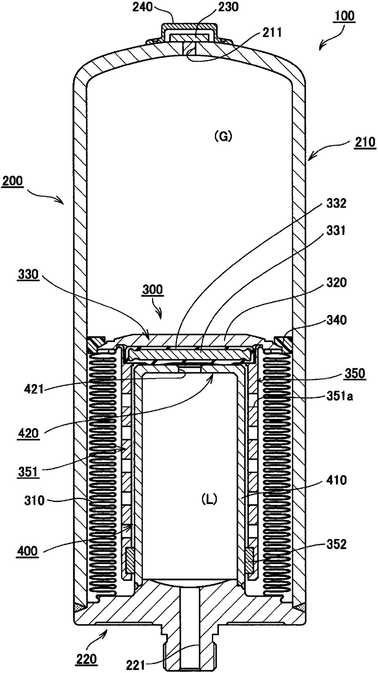
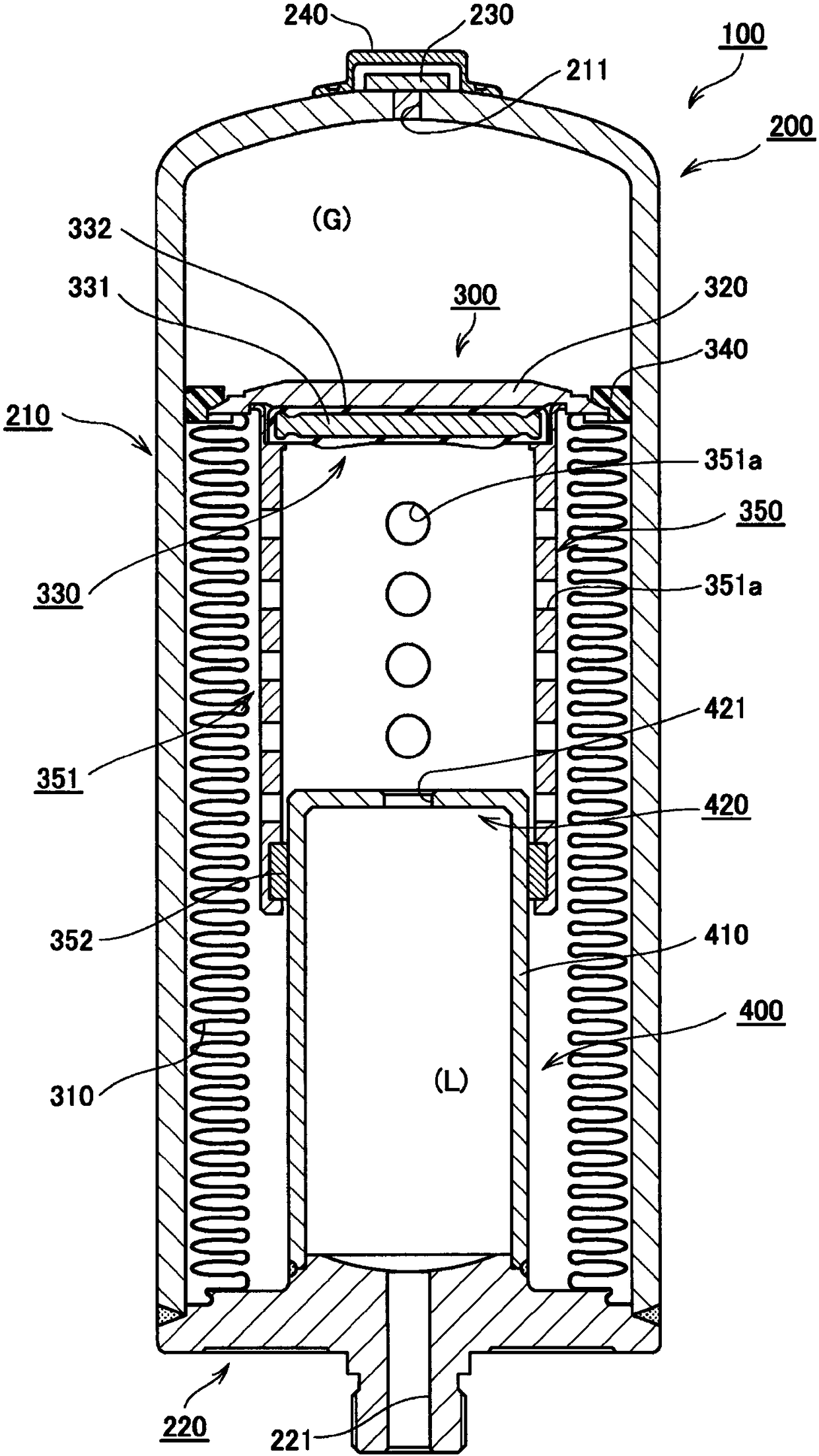
[0050] refer to figure 1 and figure 2 The accumulator according to Embodiment 1 of the present invention will be described. figure 1 and figure 2 It is a schematic cross-sectional view of the accumulator involved in Embodiment 1 of the present invention, figure 1 Indicates the shortened state of the metal bellows, figure 2 Indicates the stretched state of the metal bellows.

[0051]

[0052] The overall structure of the accumulator according to Embodiment 1 of the present invention will be described. The accumulator 100 according to this embodiment can be used to release a large amount of energy in a short time, to moderate pressure fluctuations, and the like. As a more specific example, it can be used, for example, to moderate pulsation in piping through which oil flows in an automobile. In addition, the accumulator 100 according to the present embodiment has a rotationally symmetrical shape with respect to the central axis except for some members (structural me...

Embodiment 2

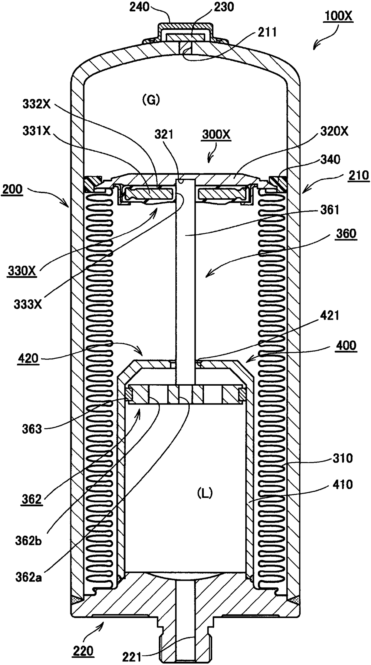
[0071] image 3 Example 2 of the present invention is shown. In the present embodiment, a structure in which the structure related to the slide unit is different from that of the first embodiment is shown. Since other structures and functions are the same as those in Embodiment 1, the same symbols are attached to the same structural parts and their descriptions are appropriately omitted. image 3 It is a schematic cross-sectional view of the accumulator according to Example 2 of the present invention, and shows a state where the metal bellows is stretched.

[0072] In the accumulator 100X of this embodiment, the structure of the sliding unit 360 is different from that of the first embodiment, and the partial shapes of the pressure vessel 200 and the bracket 400 are different, but the basic structure and function are the same as those of the first embodiment.

[0073] As in the case of the first embodiment, the partition unit 300X according to the present embodiment also incl...

Embodiment 3

[0081] Figure 4 Example 3 of the present invention is shown. This embodiment shows a structure in which the structure of the sliding unit is different from that of the first embodiment. Since other structures and functions are the same as those in Embodiment 1, the same symbols are attached to the same structural parts and their descriptions are appropriately omitted. In addition, the same structural parts as in the second embodiment are given the same symbols and their descriptions are appropriately omitted. Figure 4 It is a schematic cross-sectional view of an accumulator according to Example 3 of the present invention, and shows a state where the metal bellows is stretched.

[0082] In the accumulator 100Y according to this embodiment, the structure of the sliding unit is different from that of the first embodiment, and the partial shapes of the pressure vessel 200 and the bracket 400 are different, but the basic structure and function are the same as those of the first...


PUM


Abstract

The present invention provides an accumulator capable of minimizing collisions of a metal bellows with a pressure container. This accumulator is characterized in that: a partitioning unit (300) is provided with a tubular metal bellows (310) fixed at one end side to a pressure container (200), the tubular metal bellows (310) expanding and contracting in accordance with pressure in a fluid chamber and pressure in a gas chamber, and a bellows cap (320) fixed to the other end side of the metal bellows (310); and the partitioning unit (300) has a seal member (330) that is provided between the bellows cap (320) and a port (221), the seal member (330) sealing in a hydraulic fluid on the fluid chamber side via the metal bellows (310) when the metal bellows (310) contracts, and a sliding unit (350)fixed to the bellows cap (320), the sliding unit (350) sliding in the expanding / contracting direction of the metal bellows (310) in relation to a stay (400).

Description

technical field [0001] The present invention relates to an accumulator for discharging a large amount of energy in a short period of time or mitigating pressure fluctuations. Background technique [0002] Until now, accumulators equipped with metal bellows have been used to release a large amount of energy in a short period of time or to moderate pressure fluctuations. In this type of accumulator, a sliding ring that also functions as a bearing is provided at the top of the metal bellows to prevent the metal bellows from colliding with the pressure vessel when the metal bellows vibrates due to external vibrations. refer to Figure 6 and Figure 7 This technique will be described. Figure 6 and Figure 7 is a schematic cross-sectional view of an accumulator involved in a conventional example, Figure 6 Indicates the shortened state of the metal bellows, Figure 7 It means that the metal bellows is stretched. [0003] The accumulator 500 according to the conventional examp...

Claims


Application Information

Patent Timeline
Patent Type & Authority Applications(China)
IPC IPC(8): F15B1/10F15B1/14
CPCF15B1/103F15B2201/205F15B2201/3153F15B2201/3157F15B2201/3158F16L55/053F15B1/14
Inventor 有川达浩
Owner EAGLE INDS
Why Eureka
Try Eureka