

Cutting device
A technology for cutting devices and cutting parts, which is applied in the direction of shearing devices, manufacturing tools, shearing machines, etc., and can solve problems such as the inability to smoothly cut off electrified parts
- Summary
- Abstract
- Description
- Claims
- Application Information
AI Technical Summary
Problems solved by technology
Method used
Image

Examples
no. 1 approach
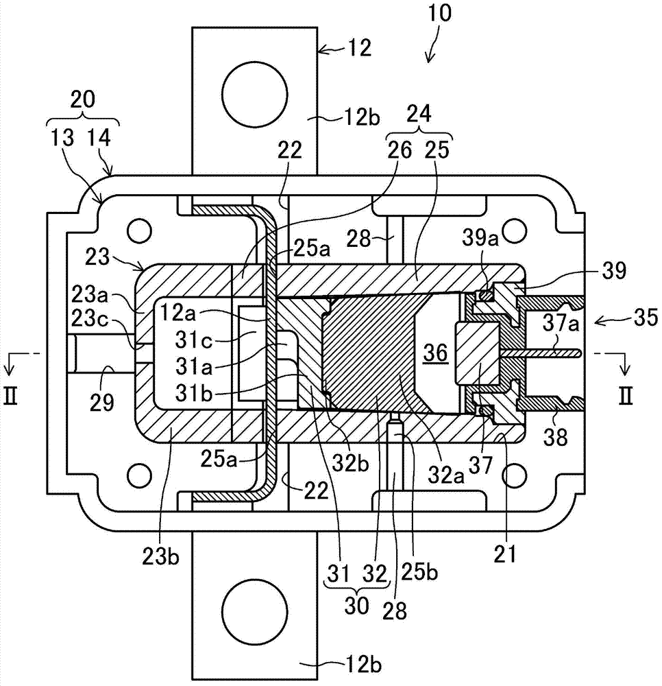
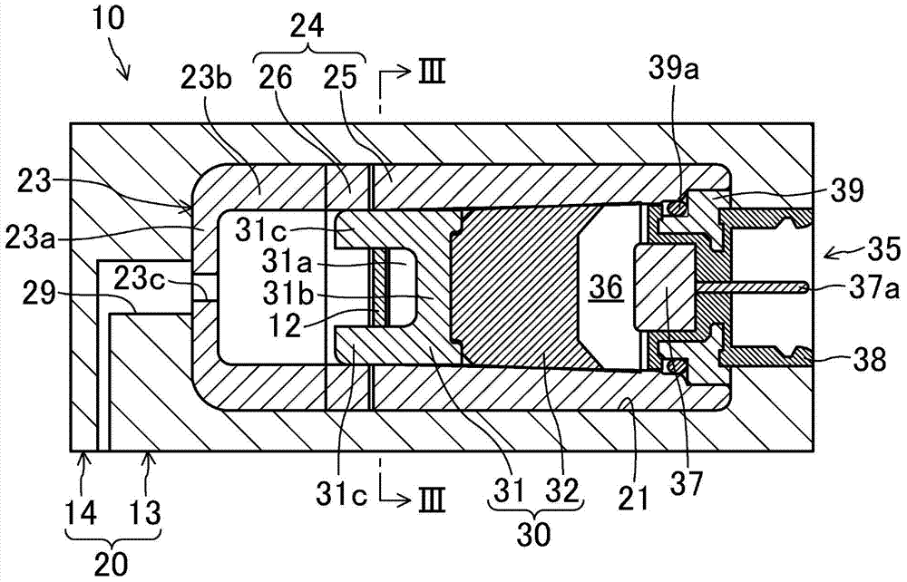
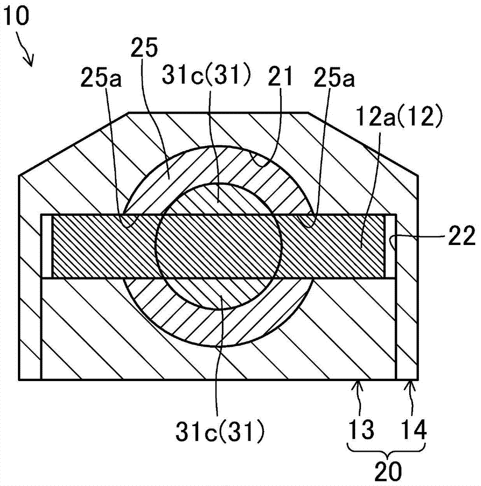
[0082] Such as Figure 1 to Figure 8 As shown, the cutting device 10 according to the first embodiment is configured to cut the energization member 12 by advancing the blade 30 by the high-pressure gas generated by the reaction of the gas generating agent. In this cutting device 10, gunpowder is used as a gas generating agent for generating high-pressure gas.
[0083] Such as Figure 1 to Figure 5 As shown, the cutting device 10 includes a resin case 20 . A stopper 23 , an inner cylinder 24 , a blade 30 , and a gas generator 35 are accommodated inside the resin case 20 .
[0084] In the following, for the convenience of description, the figure 2 The left side of the left-right direction in the figure 2 The right side of the left-right direction in the figure 2 The upper side of the up and down direction in the figure 2 The lower side in the up-down direction in is described as "lower side". Additionally, with figure 2 The front side in the direction perpendicular ...
no. 2 approach
[0154] Next, this second embodiment will be described. Such as Figure 16 and Figure 17 As shown, the cutting device 10 of the present embodiment is obtained by changing the configuration of the energization member 12 in the cutting device 10 of the first embodiment described above. That is, in the second embodiment, an engaging portion is provided instead of the high voltage portion in the first embodiment.
[0155] Specifically, the U-shaped portion 12 a of the current conduction member 12 has a substrate 120 a inserted into the slot 25 a of the first cylindrical member 25 . The base plate 120 a is a straight plate member extending in the radial direction of the first cylindrical member 25 . A widened portion 121 a is formed on the base plate 120 a, and the widened portion 121 a is located outside the slot 25 a in the radial direction of the first cylindrical member 25 . The width L2 of the widened portion 121a is greater than the width L1 of the slot 25a. The width of...
no. 3 approach
[0186] Next, this third embodiment will be described. Such as Figure 24 As shown, the third embodiment is a circuit breaker 50 including the disconnecting device 10 according to the present invention.
[0187] The above-mentioned circuit breaker 50 includes: a load-side terminal 55 and a power-side terminal 54 provided in a resin case (not shown in the figure), and a terminal composed of a current-carrying member 12 for connecting the load-side terminal 55 and the power-side terminal 54 . Between parts 51.
[0188] The inter-terminal member 51 includes a fixed contact 52 connected to a load-side terminal 55 and a movable contact 53 connected to a power-side terminal 54 . The movable contact 53 is provided to be movable between a contact position in contact with the fixed contact 52 and a non-contact position away from the fixed contact 52 . When the movable contact 53 moves to the contact position, the movable contact 53 a of the movable contact 53 comes into contact with ...
PUM
 Abstract
Description
Claims
Application Information