Method and system for transitioning a communication circuit to a low-power state

a communication circuit and low-power technology, applied in the field of low-power state transitioning a communication circuit, can solve the problems of insufficient energy efficiency of conventional solutions used to implement communication over ethernet links, inconvenient operation, and large energy consumption of conventional solutions for transmitting and receiving data, so as to achieve less heat, less energy consumption, and more energy-efficient communication

Active Publication Date: 2015-03-24
ALTERA CORP
View PDF3 Cites 6 Cited by
  • Summary
  • Abstract
  • Description
  • Claims
  • Application Information

AI Technical Summary

Benefits of technology

[0006]Accordingly, a need exists for more energy efficient communication over a communication link, particularly using communication circuitry implemented using one or more programmable logic devices (PLDs) such field-programmable gate arrays (FPGAs). A need also exists to enable communication over a communication link in a more cost-effective manner. Further, a need exists to generate less heat while enabling communication over a communication link. Embodiments of the present invention provide novel solutions to these needs and others as described below.

Problems solved by technology

Although Ethernet is a useful way to communicate data, conventional solutions for transmitting and receiving data consume a relatively large amount of energy.
For example, circuitry at both the transmitting and receiving ends of the Ethernet consume power regardless of whether data is being transmitted over the Ethernet link or not.
Thus, conventional solutions used to implement communication over an Ethernet link are not always energy efficient, and therefore, costly.
Furthermore, in backplane applications where a significant number of devices are housed together in close proximity to one another, the amount of heat generated by the circuitry used to implement communication over the Ethernet link can adversely affect system performance and reliability.
Additionally, high ambient air temperature caused by the Ethernet circuitry can increase the failure rate of system components.

Method used


Image

  • Method and system for transitioning a communication circuit to a low-power state
  • Method and system for transitioning a communication circuit to a low-power state
  • Method and system for transitioning a communication circuit to a low-power state

Examples


Embodiment Construction

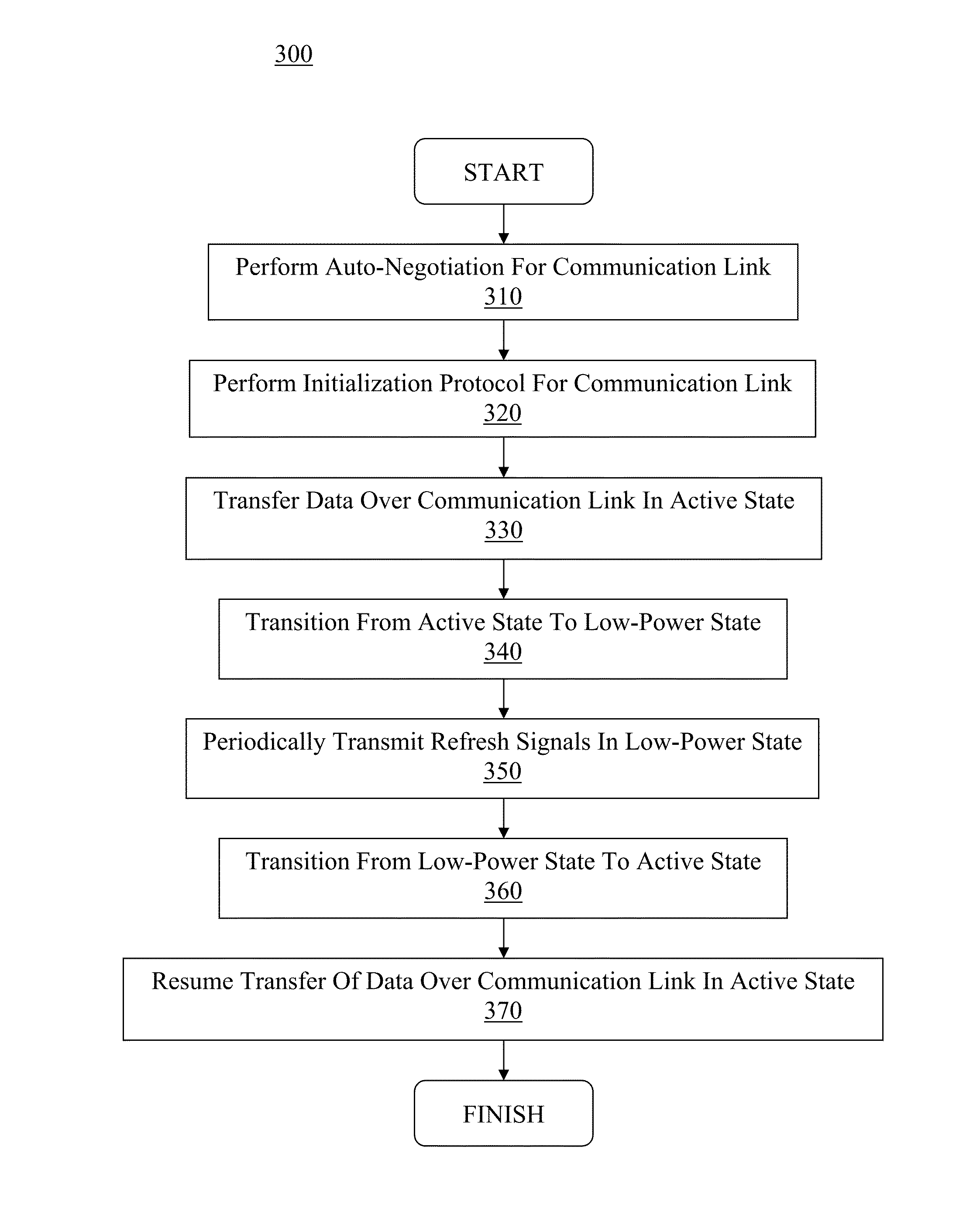
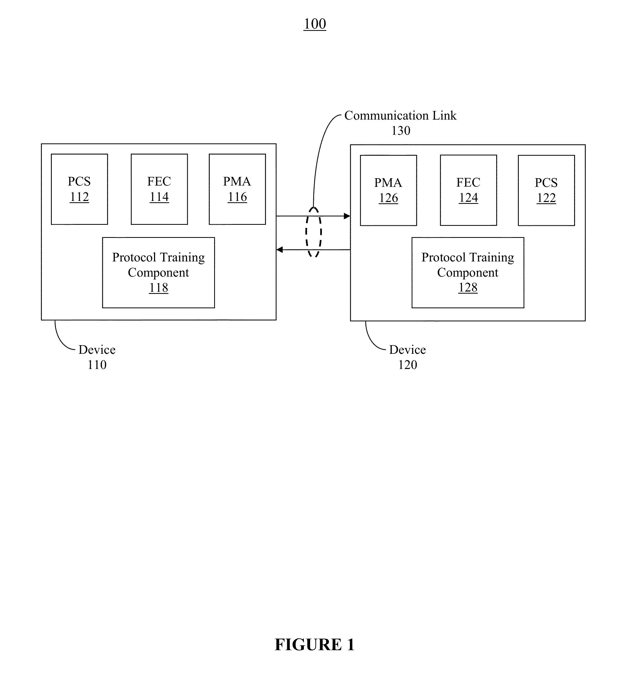
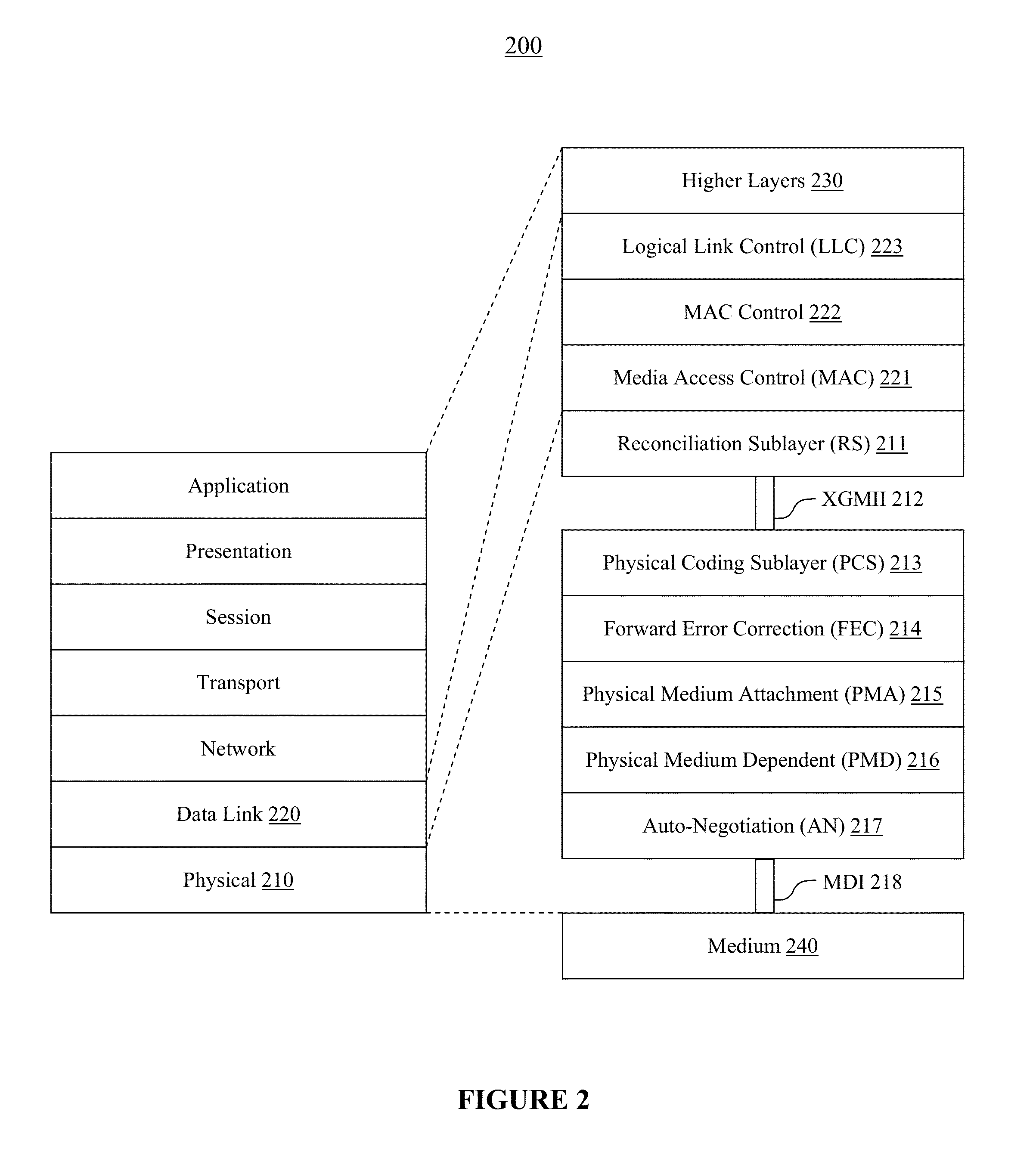
[0029]Reference will now be made in detail to embodiments of the present invention, examples of which are illustrated in the accompanying drawings. While the present invention will be discussed in conjunction with the following embodiments, it will be understood that they are not intended to limit the present invention to these embodiments alone. On the contrary, the present invention is intended to cover alternatives, modifications, and equivalents which may be included with the spirit and scope of the present invention as defined by the appended claims. Furthermore, in the following detailed description of the present invention, numerous specific details are set forth in order to provide a thorough understanding of the present invention. However, embodiments of the present invention may be practiced without these specific details. In other instances, well-known methods, procedures, components, and circuits have not been described in detail so as not to unnecessarily obscure aspect...


PUM


Abstract

A method and system for transitioning a communication circuit to a low-power state are disclosed. Where a first device and a second device communicate over a communication link, the first device may initiate a transition from an active state to a low-power state to conserve energy. A symbol may be encoded by the first device in data and transmitted to the second device. The first device may deactivate one or more components when entering the low-power state. Additionally, responsive to receiving and decoding the symbol, the second device may deactivate one or more components when entering the low-power state. In this manner, energy consumption of one or more components can be reduced and a low-power state may be entered to conserve energy.

Description

RELATED APPLICATIONS[0001]The present application is related to U.S. patent application Ser. No. 13 / 175,740, filed Jul. 1, 2011, entitled “METHOD AND SYSTEM FOR REFRESHING A COMMUNICATION CIRCUIT DURING A LOW-POWER STATE,” naming Divya Vijayaraghavan and Chong Lee as inventors. That application is incorporated herein by reference in its entirety and for all purposes.[0002]The present application is related to U.S. patent application Ser. No. 13 / 175,745, filed Jul. 1, 2011, entitled “METHOD AND SYSTEM FOR EFFICIENTLY TRANSITIONING A COMMUNICATION CIRCUIT FROM A LOW-POWER STATE,” naming Divya Vijayaraghavan and Chong Lee as inventors. That application is incorporated herein by reference in its entirety and for all purposes.BACKGROUND OF THE INVENTION[0003]Ethernet networks are commonly used to exchange data. For example, computer systems may be coupled via Ethernet links, where the links may include twisted-pair cabling or some other communication medium. As another example, Ethernet ...

Claims


Application Information

Patent Timeline
Patent Type & Authority Patents(United States)
IPC IPC(8): H04L27/00
CPCH04W52/0229H04W52/0235H04W52/028Y02D30/70
Inventor VIJAYARAGHAVAN, DIVYALEE, CHONG H.
Owner ALTERA CORP
Why Eureka
Try Eureka