Conveyor belt wear detection apparatus

a technology of wear detection and conveyor belt, which is applied in the direction of magnetic variables, instruments, transportation and packaging, etc., can solve the problems of belt unusability, failure of detection, deterioration in accuracy, etc., and achieve the effect of high accuracy, accurate estimation of the degree of advance of wear, and suppression of the peeled area

Inactive Publication Date: 2015-03-31
BRIDGESTONE CORP
View PDF17 Cites 9 Cited by
  • Summary
  • Abstract
  • Description
  • Claims
  • Application Information

AI Technical Summary

Benefits of technology

[0019]According to the conveyor belt wear detection apparatus of the present invention, the rubber magnet includes a plate-like diagonal portion and a plate-like parallel portion which are both magnetized in a thickness direction, the diagonal portion extending in a conveyor belt width direction while linearly extending, in section in a conveyor belt length direction, from an outer side end, which is closer to the front-side surface, to an inner side end, which is away from the front-side surface, while being at an angle to the front-side surface, the parallel portion being formed continuously from the inner side end of the diagonal portion and being arranged parallel to the front-side surface. With this configuration, due to the magnet volume of the parallel portion, there can be generated a magnetic field that is strong enough to be detected by the magnetic sensor even until the diagonal portion is almost worn away. Therefore, the degree of advance of the wear can be estimated with accuracy even when excessive wear is underway.
[0020]Further, in the conveyor belt wear detection apparatus according to another aspect of the present invention, the diagonal portion is disposed so that the inner side end comes ahead of the outer side end with respect to a conveyor belt transport direction. With this configuration, even when the rubber peels off from the magnet from the outer-side end of the diagonal portion during running of the conveyor belt, the peeled area can be suppressed to minimum.
[0021]Still further, in the conveyor belt wear detection apparatus according to further another aspect of the present invention, the arithmetic section can estimate with high accuracy, upon detection of a magnetic field, the thickness of the conveyor belt having undergone wear from the front-side surface, by using, for example, a function D=f(Rx / R0) between a thickness D of the conveyor belt and a ratio (Rx / R0) of a waveform width Rx to an initial waveform width R0, which is obtained in advance from experiment, based on the ratio (Rx / R0) of the waveform width Rx to an initial waveform width R0, in which the waveform width Rx is obtained, in a time variation pattern of a magnetic field detected by the magnetic sensor, at a threshold value predetermined as a specific sensor output value and the initial waveform width R0 is obtained at the threshold value in a time variation pattern detected for the conveyor belt that has not been subjected to wear.
[0022]Yet further, the conveyor belt wear detection apparatus according to another aspect of the present invention further includes a reference magnet for correcting a waveform width of an output waveform detected by the rubber magnet, the reference magnet being disposed either on the front side or on the rear side of the rubber magnet in a conveyor belt transport direction. The reference magnet is capable of correcting a waveform width of an output waveform detected from the rubber magnet, to thereby ensure the accuracy of the measurement result without deteriorating the measurement accuracy.
[0023]Furthermore, in the conveyor belt wear detection apparatus according to yet another aspect of the present invention, the rubber magnet is formed of magnetic powder which is dispersed in a rubber material matrix and magnetized. Therefore, the rubber magnet is capable of flexibly following deformation of the conveyor belt which is deformed during use, to thereby ensure durability while maintaining a strong magnetic force.

Problems solved by technology

In doing maintenance of a conveyor belt for successively transporting an object such as charcoal, it is extremely important to detect and monitor a wear amount on a front-side surface of the conveyor belt because the front-side surface forming an outer peripheral surface that comes into direct contact with the object to be transported is subjected wear that advances with time due to friction against the object to be transported, which eventually makes the belt unusable.
Then, in the apparatus, when the wear is advanced further enough to expose the stair-like magnet 93 on the surface, the diagonal magnet 92 is diminished in length, resulting in weakening of the magnetic field from the diagonal magnet 92, which may leads to a failure in detection and a deterioration in accuracy.

Method used


Image

  • Conveyor belt wear detection apparatus
  • Conveyor belt wear detection apparatus
  • Conveyor belt wear detection apparatus

Examples


first embodiment

[0034]In the following, embodiments of the present invention are described with reference to the drawings. FIG. 3 is side view of a conveyor belt in a conveyor belt wear detection apparatus according to a first embodiment of the present invention, FIG. 4 is an enlarged sectional view of the portion b of FIG. 3, and FIG. 5 is a view taken along the arrow C-C in FIG. 3.

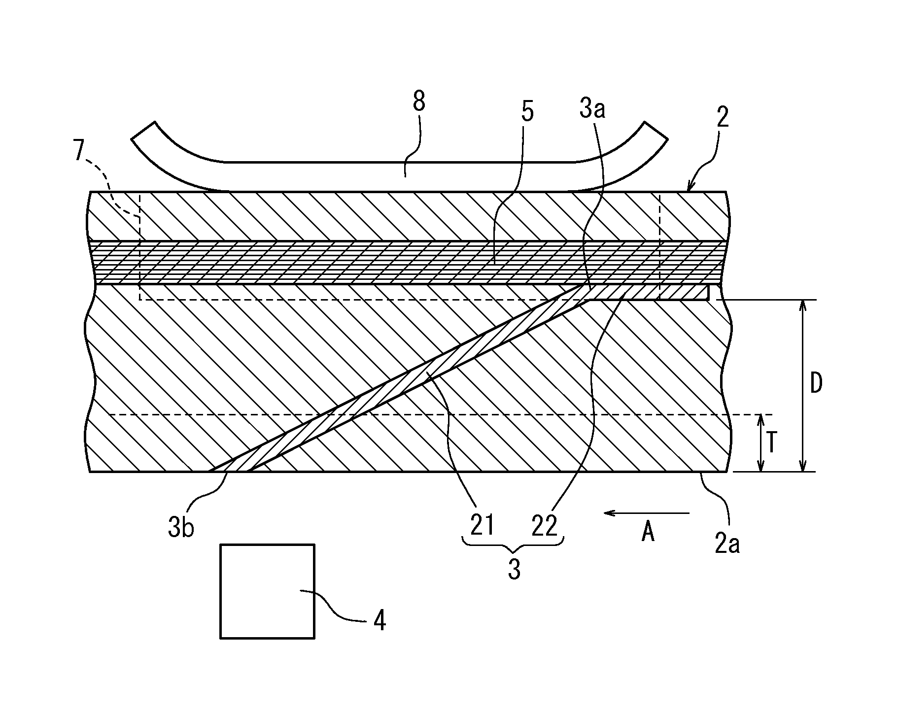
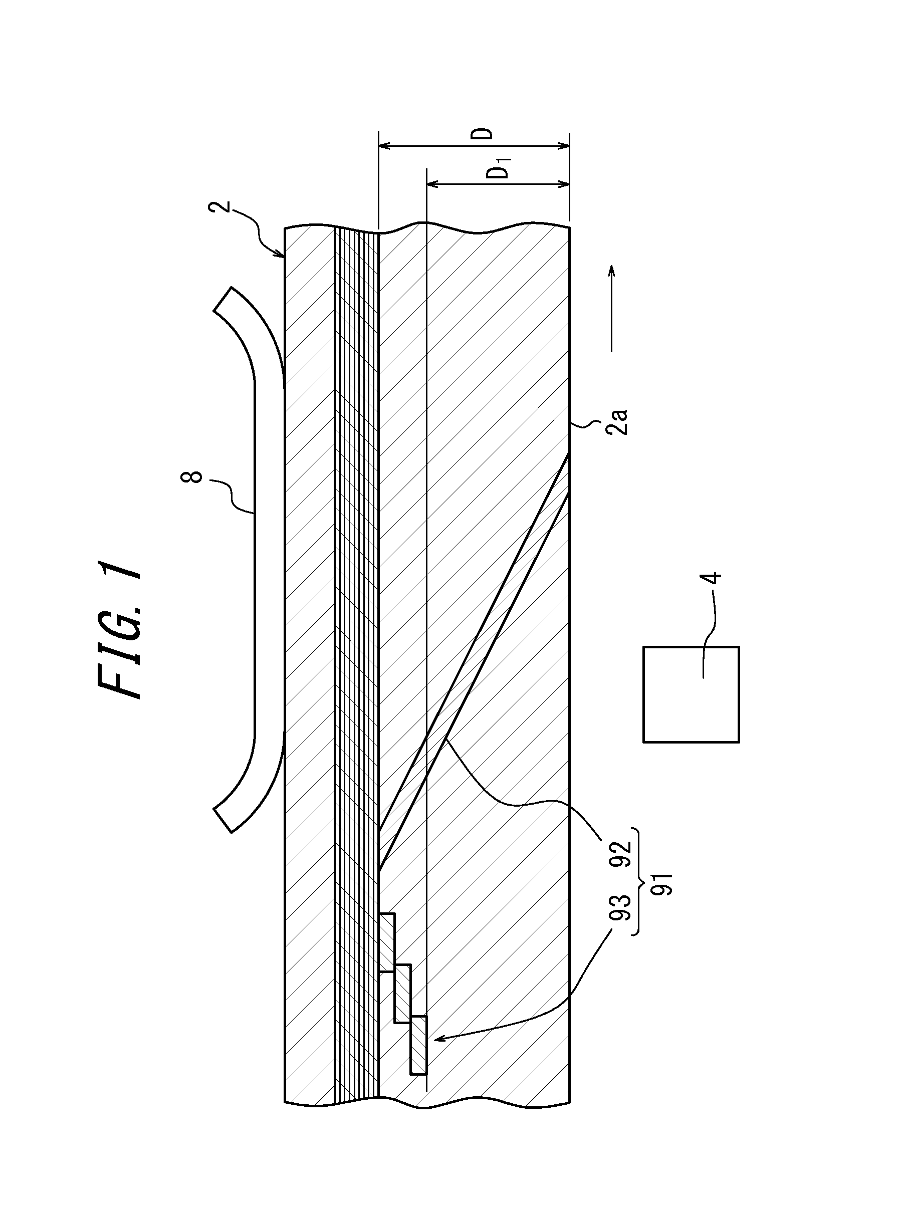
[0035]The wear detection apparatus includes: a rubber magnet 3, which is embedded on a front-side surface 2a side of a conveyor belt 2 looped around a pulley 1; and a magnetic sensor 4, which is disposed in proximity to the front-side surface 2a and detects a magnetic field from the rubber magnet 3.

[0036]The rubber magnet 3 extends in a conveyor belt width direction and includes a plate-like diagonal portion 21 and a plate-like parallel portion 22, which are both magnetized in the thickness direction. The diagonal portion 21 linearly extends, in section in a conveyor belt length direction, from an outer side end 3b, whi...

second embodiment

[0043]FIG. 7 is a sectional view along a belt longitudinal direction of a conveyor belt according to a second embodiment of the present invention. As illustrated in FIG. 7, a conveyor belt 30 has a configuration similar to that of the conveyor belt 2 of the first embodiment (see FIG. 4), except that the conveyor belt 30 has, on both sides thereof in the belt longitudinal direction, a trigger magnet 31 and a reference magnet 32 which are disposed as being in close contact with the reinforcement 5 as a core of the belt and embedded on the front-side surface 30a side.

[0044]Here, the trigger magnet 31 is arranged ahead of the rubber magnet 3 in the conveyor belt transport direction, so as to have, for example, the south pole on the front side in the belt transport direction and the north pole on the rear side in the belt transport direction. As a result, during running of the conveyor belt 30, the trigger magnet 31 passes through, ahead of the rubber magnet 3, a magnetic field detection...


PUM


Abstract

A rubber magnet (3) includes a plate-like diagonal portion (21) and a plate-like parallel portion (22) which are both magnetized in a thickness direction, the diagonal portion (21) extending in a conveyor belt width direction while linearly extending, in section in a conveyor belt length direction, from an outer side end (3b), which is closer to the front-side surface (2a), to an inner side end (3a), which is away from the front-side surface (2a), while being at an angle to the front-side surface (2a), the parallel portion (22) being formed continuously from the inner side end (3a) of the diagonal portion, so as to be arranged parallel to the front-side surface (2a).

Description

CROSS REFERENCE TO RELATED APPLICATION[0001]This application is a National Stage of International Application No. PCT / JP2010 / 006643 filed Nov. 11, 2010, claiming priority based on Japanese Patent Application No. 2009-258101 filed Nov. 11, 2009, the contents of all of which are incorporated herein by reference in their entirety.TECHNICAL FIELD[0002]The present invention relates to a conveyor belt wear detection apparatus which includes a rubber magnet embedded in a conveyor belt, a magnetic sensor which is disposed in proximity to the front-side surface forming an outer peripheral surface of the conveyor belt and detects a magnetic field from the rubber magnet, and an arithmetic section for estimating, based on a signal from the magnetic sensor, a wear amount on the front-side surface of the conveyor belt, and more particularly, to a conveyor belt wear detection apparatus capable of detecting a wear amount even when the wear amount is closer to the wear limit.RELATED ART[0003]In doin...

Claims


Application Information

Patent Timeline
Patent Type & Authority Patents(United States)
IPC IPC(8): B65G43/02
CPCB65G43/02
Inventor NAKAMURA, TOMOKISAKAGUCHI, TOSHIKI
Owner BRIDGESTONE CORP
Why Eureka
Try Eureka