Vehicle with aerial and ground mobility

a technology of vehicle and ground, applied in the direction of spoked wheels, aircraft convertible vehicles, transportation and packaging, etc., can solve the problems of limited operating time, ground vehicles have a much longer operating time, and have difficulty accessing elevated areas, etc., to achieve maneuverability, vehicle is unable to fly, and the effect of limited operating tim

Active Publication Date: 2015-03-31
ZENON DRAGAN
View PDF17 Cites 113 Cited by
  • Summary
  • Abstract
  • Description
  • Claims
  • Application Information

AI Technical Summary

Benefits of technology

[0013]During flight the wheel is stationary while the rotor spins inside the wheel, such that any debris picked up by the wheels does not affect the balance of the rotor. The mass that is rotated at high speed for flying mode is also much reduced compared to the prior art, reducing power requirements. The stationary wheel also serves to protect the rotor from contact with building walls or like objects during flight.

Problems solved by technology

Aerial vehicles, commonly electric battery powered hovering vehicles with spinning rotors for lift and propulsion, have the ability to access elevated areas like windows and roof tops and provide a wide range of observation, but have a limited operating time due to the high energy requirements of flight and the weight of batteries.
Ground vehicles have a much longer operating time but have difficulties accessing elevated areas, and maneuvering over stairs and like obstacles.
A problem with the Kuntz vehicle is that in ground mode, the wheel treads will often pick up debris which unbalances the rotor / wheel assembly and which can make the vehicle unable to fly.
Further since the annular covering spins with the rotors, any contact with walls or the like during flight can damage the rotor.
Even slight contact can slow the rotor such that control is difficult, and can also upset the balance of the rotor and adversely affect flying.

Method used


Image

  • Vehicle with aerial and ground mobility
  • Vehicle with aerial and ground mobility
  • Vehicle with aerial and ground mobility

Examples


Embodiment Construction

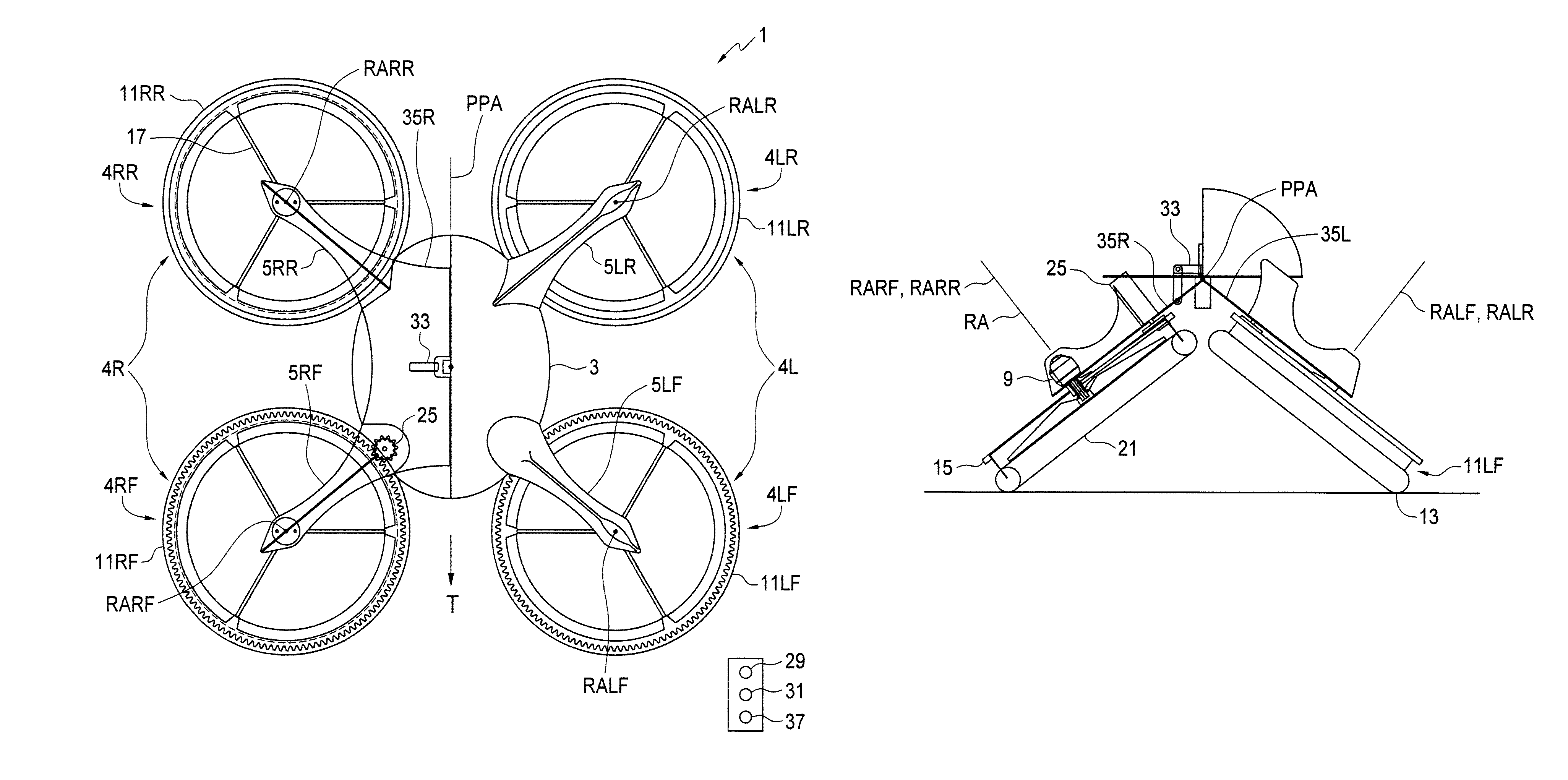
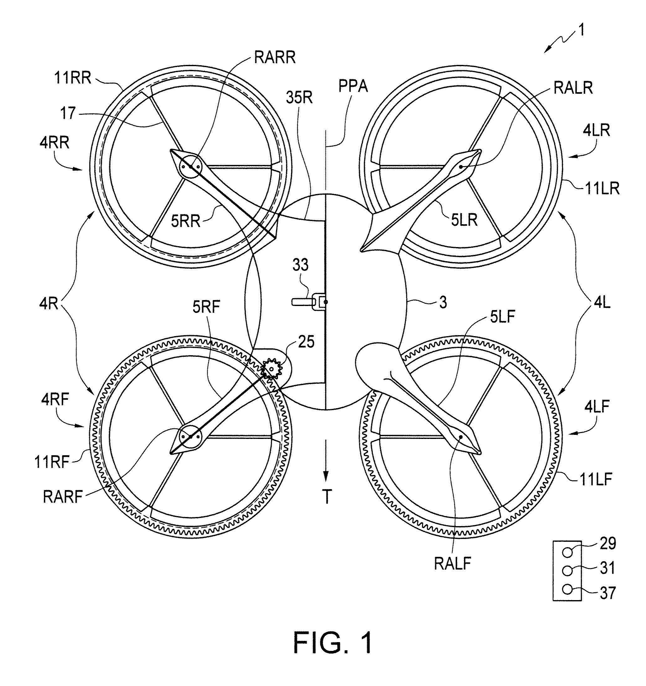
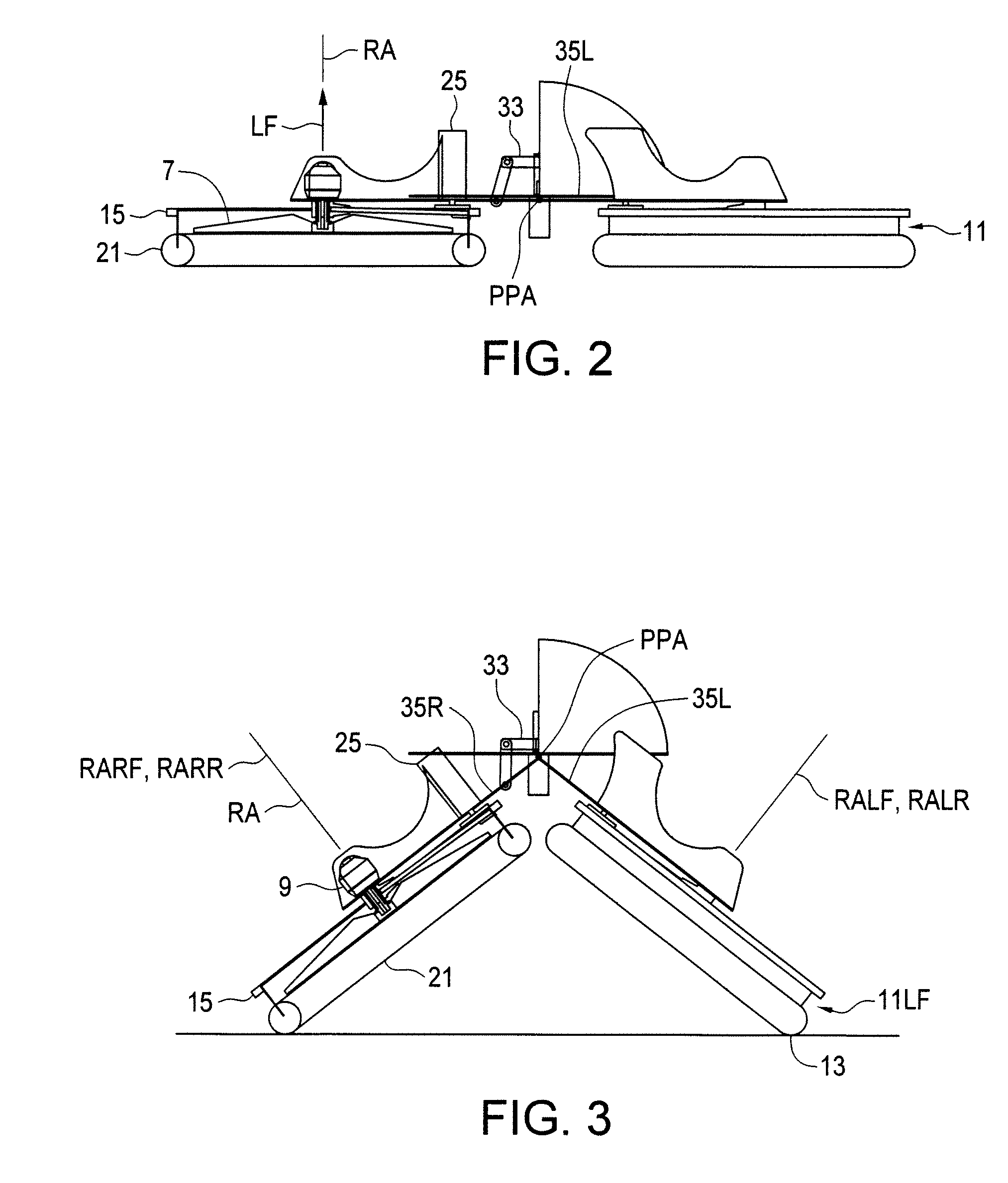
[0033]FIGS. 1-3 schematically illustrate an embodiment of an unmanned vehicle apparatus 1 of the present invention. The apparatus 1 comprises a vehicle body 3 and right and left rotor and wheel assemblies 4R, 4L extending from corresponding right and left sides of the vehicle body 3.

[0034]Each rotor and wheel assembly 4, as schematically illustrated in FIGS. 4 and 5, comprises a rotor arm 5 adapted to be attached at an inner end thereof to the vehicle body 3, and a rotor 7 rotatably connected to an outer end of the rotor arm 5 about a rotor axis RA, and a rotor drive is mounted on the rotor arm operative to rotate the rotor 7 such that the rotor exerts an upward lift force LF on the rotor arm 5 in the direction of the rotational axis RA. In the illustrated apparatus 1 the rotor drive is provided by a rotor motor 9 mounted on the rotor arm 5 and connected directly to the rotor 7. An open spoked wheel 11 is rotatably connected to the outer end of the rotor arm 5 about the rotor axis R...


PUM


Abstract

A combination rotor and wheel assembly for an unmanned vehicle with ground and aerial mobility has a rotor arm adapted to be attached at an inner end thereof to a vehicle body. A rotor is rotatably connected to an outer end of the rotor arm about a rotor axis, and a rotor drive mounted on the rotor arm rotates the rotor such that the rotor exerts an upward lift force on the rotor arm. An open spoked wheel is rotatably connected about the rotor axis independent of the rotor The diameter of the wheel is greater than that of the rotor, and a bottom edge of the wheel is below the rotor. A wheel drive rotates the wheel. Vehicles can have various numbers and orientations of the rotor and wheel assembly to provide aerial and ground mobility.

Description

[0001]This invention is in the field of unmanned vehicles (UMV) and in particular a UMV that has both the capabilities of an unmanned aerial vehicle (UAV) and of an unmanned ground vehicle (UGV), and thus can both fly and roll along the ground.BACKGROUND[0002]Remote controlled unmanned vehicles are well known for use in military and police surveillance, bomb disposal, disaster investigation, and the like. Most commonly these UMVs are unmanned ground vehicles (UGV) which have the ability to travel only along the ground, or unmanned aerial vehicles (UAV) which have the ability to travel only in the air.[0003]Aerial vehicles, commonly electric battery powered hovering vehicles with spinning rotors for lift and propulsion, have the ability to access elevated areas like windows and roof tops and provide a wide range of observation, but have a limited operating time due to the high energy requirements of flight and the weight of batteries. Such an aerial vehicle is disclosed for example i...

Claims


Application Information

Patent Timeline
Patent Type & Authority Patents(United States)
IPC IPC(8): B64C37/00B60B1/00B60F5/02
CPCB60F5/02B60B1/00B64C2201/162B64C2201/126B64C2201/027B60Y2200/80B64C39/024B64C37/00B64C25/36B64U10/13B64U30/20B64U50/14B64U50/19B64U2101/00B64C39/005
Inventor OLM, ORVILLEWOOD, GREGDRAGAN, ZENON
Owner ZENON DRAGAN
Why Eureka
Try Eureka