Helicopter with blade-tip thrusters and annular centrifugal fuel supply tank and concentric cabin and fuselage

a technology of blade-tip thrusters and fuel supply tanks, applied in the field of aircraft, can solve the problems of inconvenient maintenance, heavy engine and transmission, etc., and achieve the effect of convenient transportation

Active Publication Date: 2015-03-31
CHARLES DOUGLAS POPE
View PDF11 Cites 17 Cited by
  • Summary
  • Abstract
  • Description
  • Claims
  • Application Information

AI Technical Summary

Benefits of technology

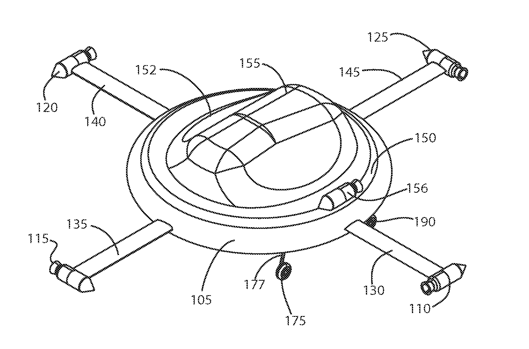
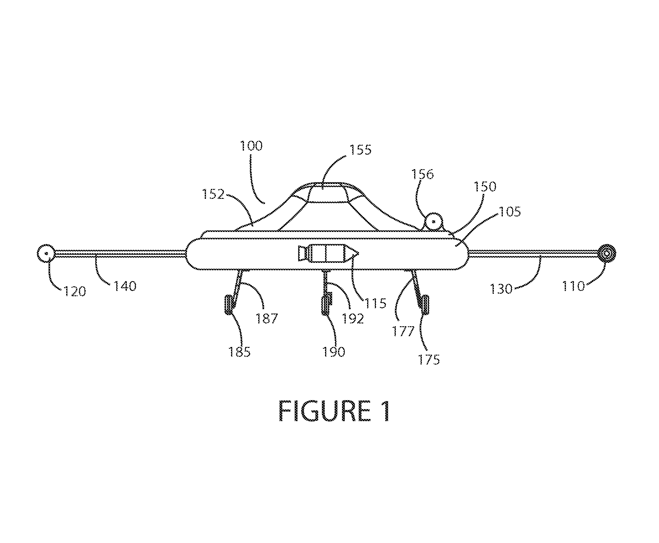
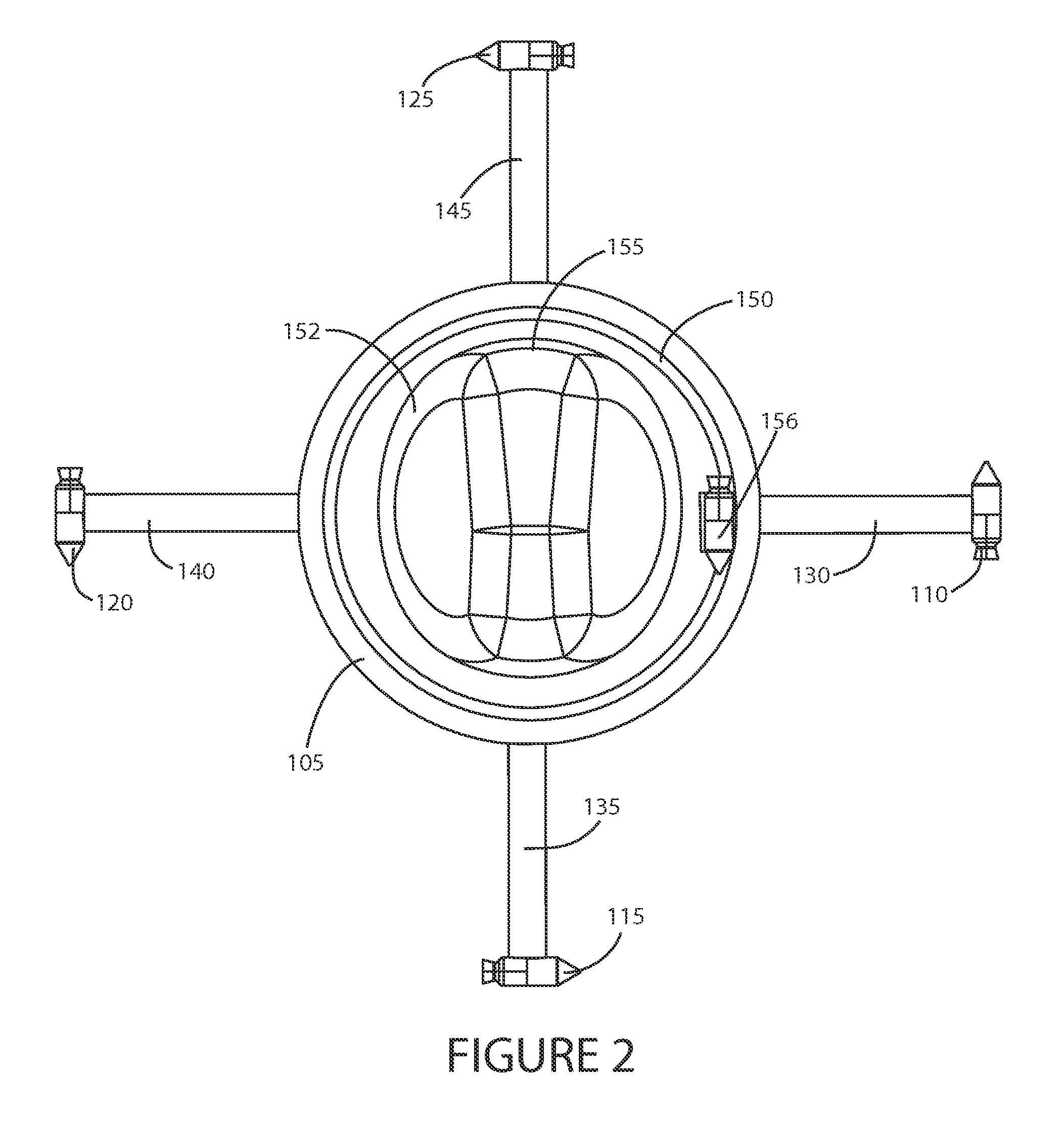
[0008]To solve one or more of the problems set forth above, in an exemplary implementation of the invention, a helicopter with blade-tip thrusters, an annular centrifugal fuel supply tank and a concentric fuselage and cabin is provided. In one embodiment, the helicopter includes a rotor comprised of a plurality of short blades with a thruster at the tip of each blade. The thruster may be an air-breathing, rocket or hybrid thruster. The blades extend from an annular fuel tank. The fuel tank comprises a hub to which the blades are attached, and rotates with the blades. Centrifugal force propels fuel from the interior compartment of the tank through conduits extending through the blades from root to tip, to the thrusters. Valves (e.g., solenoid valves and / or a flyweight governor) may be provided to regulate fuel flow to achieve and maintain a determined steady rotational speed. A fuselage covered by a canopy with a fuselage support flange is mounted atop a bearing assembly on the annular fuel tank. The pitch of each blade may be adjusted collectively and cyclically using a swash ring and linear actuators (e.g., hydraulic servos). Landing gear supports the helicopter above ground and facilitates transportation.

Problems solved by technology

Unfortunately, both the engine and transmission are heavy, bulky and inefficient due to frictional losses.
The engine and transmission are also expensive and difficult to maintain.
Another shortcoming of conventional helicopters is instability.

Method used


Image

  • Helicopter with blade-tip thrusters and annular centrifugal fuel supply tank and concentric cabin and fuselage
  • Helicopter with blade-tip thrusters and annular centrifugal fuel supply tank and concentric cabin and fuselage
  • Helicopter with blade-tip thrusters and annular centrifugal fuel supply tank and concentric cabin and fuselage

Examples


Embodiment Construction

[0046]Referring to FIGS. 1 to 4 an exemplary helicopter 100 includes a rotor comprised of a plurality of short blades 130, 135, 140, 145 with a thruster 110, 115, 120, 125 at the tip of each blade 130, 135, 140, 145. The thruster 110, 115, 120, 125 may be an air-breathing, rocket or hybrid thruster. The blades 130, 135, 140, 145 extend from annular fuel tank 105. The fuel tank 105 comprises a hub to which the blades 130, 135, 140, 145 are attached, and rotates with the blades 130, 135, 140, 145. Centrifugal force propels fuel from an interior compartment of the tank 105, through conduits extending through the blades 130, 135, 140, 145 from root to tip, to the thrusters 110, 115, 120, 125. Valves (e.g., solenoid valves and / or a flyweight governor) may be provided to regulate fuel flow to achieve and maintain a determined steady (or approximately steady) rotational speed during flight. The valves may be part of valve assemblies that include manifolds to redirect some fuel to one or mo...


PUM


Abstract

A helicopter includes a rotor with short blades and tip thrusters. The blades extend from an annular fuel tank that rotates with the blades. Centrifugal force propels fuel from the interior compartment of the annular tank, through conduits extending through the blades from root to tip, to the tip thrusters. Valves (e.g., solenoid valves and/or a flyweight governor) regulate fuel flow to achieve and maintain a determined steady rotational speed. A fuselage covered by a canopy is mounted atop a bearing on the annular fuel tank. The pitch of each blade may be adjusted collectively and cyclically using a swash ring and hydraulic linear actuators.

Description

RELATED APPLICATION[0001]This application is a nonprovisional of and claims the benefit of priority of U.S. Provisional Application No. 61 / 712,796 filed Oct. 11, 2012, the entire contents of which are incorporated herein by this reference.FIELD OF THE INVENTION[0002]This invention relates generally to aircraft, and, more particularly, to a helicopter with blade-tip thrusters and annular centrifugal fuel supply tank and concentric cabin and fuselage.BACKGROUND[0003]Conventional helicopters include elaborate and heavy engine and transmission systems to provide power to drive a rotor and anti-torque system and to transmit torque from an output shaft of the engine to main and tail rotor assemblies. Unfortunately, both the engine and transmission are heavy, bulky and inefficient due to frictional losses. The engine and transmission are also expensive and difficult to maintain.[0004]Another shortcoming of conventional helicopters is instability. A tail rotor assembly or other comparable a...

Claims


Application Information

Patent Timeline
Patent Type & Authority Patents(United States)
IPC IPC(8): B64C27/00B64C27/06B64C27/08B64C27/72B64C27/82B64C39/00B64D37/04B64D37/06
CPCB64C39/001B64C27/06B64C27/08B64D37/06B64C27/82B64D37/04B64C27/72B64C27/18B64C27/605B64C2027/8245
Inventor POPE, CHARLES DOUGLASELLIOTT, RALPH
Owner CHARLES DOUGLAS POPE
Why Eureka
Try Eureka