Crawler bushing and crawler link device

a technology of crawler link and crawler bushing, which is applied in the direction of ring springs, vehicle cleaning, driving chains, etc., can solve the problems of time-consuming replacement of wear-resistant plates, impaired sealing function, and early wear of seals, so as to achieve stable sealing function, easy removal, and easy maintenance for recovery of sealing functions

Active Publication Date: 2015-03-31
KOMATSU LTD
View PDF26 Cites 7 Cited by
  • Summary
  • Abstract
  • Description
  • Claims
  • Application Information

AI Technical Summary

Benefits of technology

[0027]In the crawler bushing of the first aspect of the invention, the first tapered surface prevents the elastic ring, which is mounted to the small-diameter cylindrical part of the crawler bushing body, from moving axially outward, and the second tapered surface prevents the seal ring, which is coupled to the small-diameter cylindrical part of the crawler bushing body through the elastic ring, from moving axially outward. Therefore, the seal ring, together with the elastic ring, is firmly secured to the crawler bushing body even when the seal ring experiences resilience from the elastic ring in response to a squeeze. For this reason, the seal member can maintain a stable sealing function on a long-term basis without being pressed by excessive force of the seal ring.
[0028]With regard to replacement of the seal ring, the seal ring can be removed easily from the crawler bushing body by detaching the seal ring from the crawler bushing body against locking force of the first tapered surface or the second tapered surface, and the seal ring can be mounted easily to the crawler bushing body by pushing the seal ring toward the crawler bushing against the resilience from the elastic ring in response to the squeeze. In this way, maintenance for recovery of the sealing function can be carried out with ease.
[0029]The crawler bushing of the first aspect of the invention can maintain the stable sealing function on a long-term basis and also enables easy maintenance for the recovery of the sealing function. Moreover, the crawler bushing is capable of preventing the axially outward movement of the elastic ring with its extremely simple structure.
[0030]The respective structures of the second and third aspects of the invention are extremely simple, and adopting these structures can prevent the axially outward movement of the seal ring.
[0031]Adopting the structure of the fourth aspect of the invention allows easy formation of the tapered surface and the projection which projects radially inward at the inner end of the seal ring to be locked by the elastic ring.
[0032]Adopting the respective structures of the fifth and sixth aspects of the invention permits simplification of the shape of the crawler bushing.
[0033]In the crawler link device of the seventh aspect of the invention, the crawler bushing of the first, second, third, fourth, fifth or sixth aspect of the invention is adopted as the crawler bushing on which the seal member is abutted, whereby the sealing function can be maintained stably on a long-term basis. Moreover, the crawler link device thus obtained allows the easy maintenance for the recovery of the sealing function.

Problems solved by technology

However, this crawler link device 100 problematically faces time-consuming replacement of wear-resistant plate 102 which is attached to crawler bushing 101 with adhesive 103.
This causes damage and early wear to seal member 116 which as a result has an impaired sealing function.
Consequently, oil leakage may problematically occur.

Method used


Image

  • Crawler bushing and crawler link device
  • Crawler bushing and crawler link device
  • Crawler bushing and crawler link device

Examples


first exemplary embodiment

[0046](First Exemplary Embodiment)

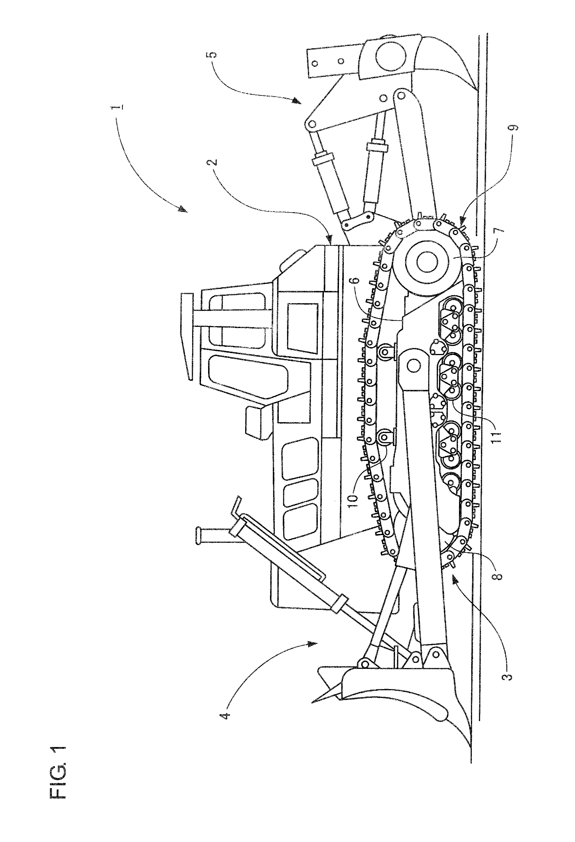
[0047](Brief Description of a Bulldozer with Reference to FIG. 1)

[0048]Bulldozer 1 shown in FIG. 1 includes vehicle body 2. Right and left sides of vehicle body 2 are provided with respective crawler units 3 (only the left crawler unit is shown). In front of vehicle body 2, blade device (front implement) 4 is disposed, while ripper device (rear implement) 5 is disposed at the back of vehicle body 2. Blade device 4 of this bulldozer 1 performs dozing and earth carrying operations, while ripper device 5 performs breaking and digging operations.

[0049](Brief Description of the Crawler Unit with Reference to FIG. 1)

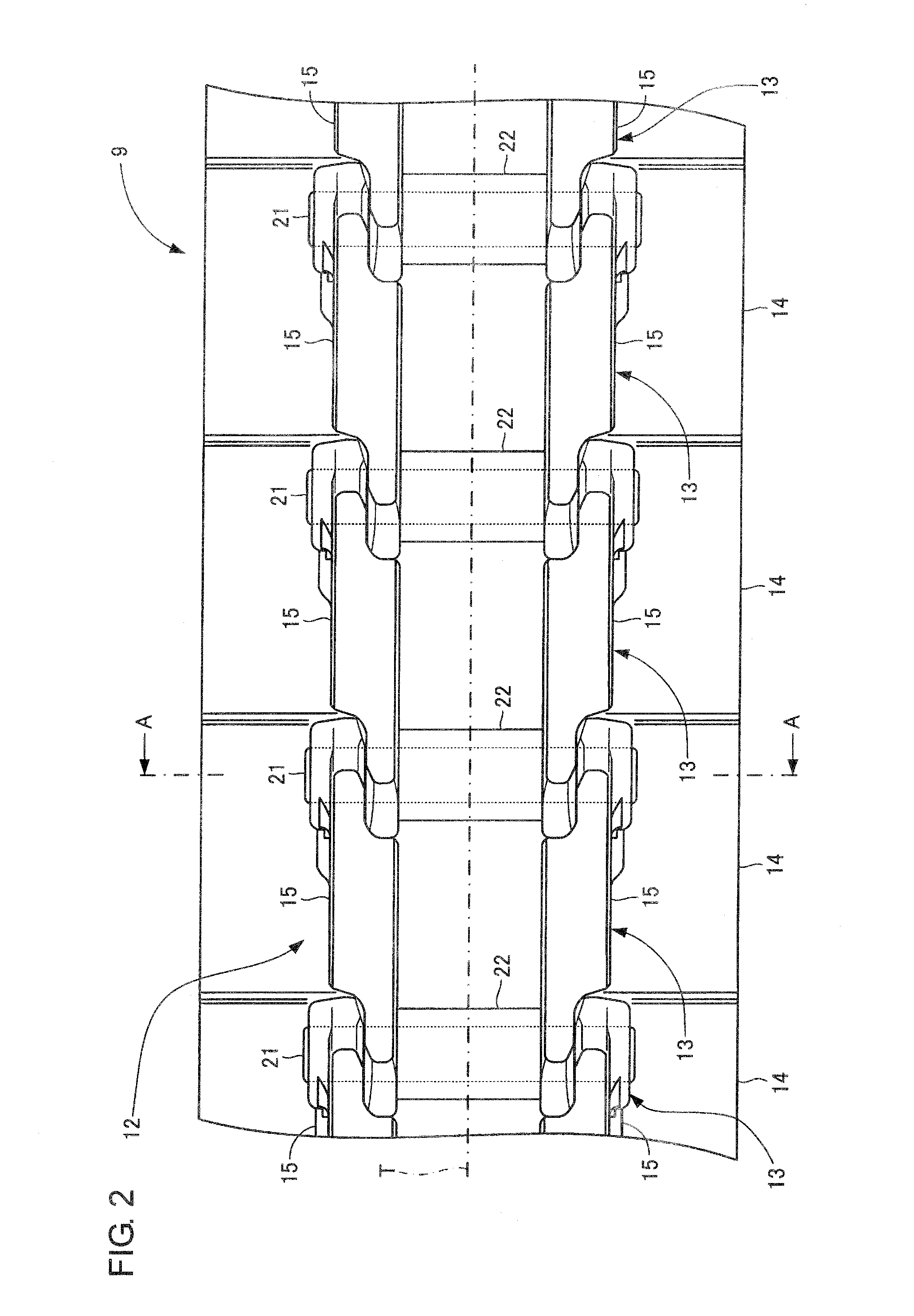
[0050]Crawler unit 3 includes track frame 6 forming a framework of crawler unit 3. Track frame 6 is disposed in front of sprocket 7, which serves as a drive wheel supported at a rear part of vehicle body 2, and extends back and forth. Idler 8 is rotatably mounted to a front part of track frame 6 to serve as an idler wheel. Crawler belt 9 servi...

second exemplary embodiment

[0116](Second Exemplary Embodiment)

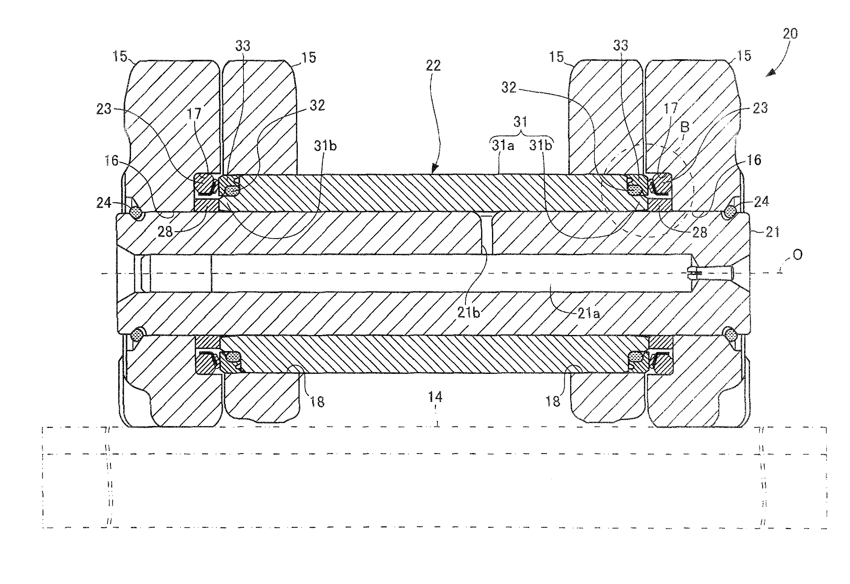
[0117]FIG. 6 is a structural illustration of a crawler bushing and a crawler link device in accordance with the second exemplary embodiment of the present invention. It is to be noted that in the second embodiment described below, elements similar to those in the first embodiment have the same reference marks in the drawing, the detailed descriptions of those elements are omitted, and emphasis is placed on different features not seen in the first embodiment.

[0118](Brief Description of a Rotary Crawler Bushing with Reference to FIG. 6)

[0119]Crawler link device 20A of the second embodiment relates to an example in which the rotary crawler bushing is adopted in crawler link device 20 of the first embodiment.

[0120]In the second embodiment, crawler bushing 50 corresponding to crawler bushing 22 of the first embodiment is a combination of first crawler bushing 51, which forms an intermediate section of crawler bushing 50 along axis O, and second crawler ...

third exemplary embodiment

[0142](Third Exemplary Embodiment)

[0143]FIG. 7 is a structural illustration of a crawler bushing and a crawler link device in accordance with the third exemplary embodiment of the present invention. It is to be noted that in the third embodiment described below, elements similar to those in the first embodiment have the same reference marks in the drawing, the detailed descriptions of those elements are omitted, and emphasis is placed on different features not seen in the first embodiment.

[0144](Description of a Cartridge Pin with Reference to FIG. 7)

[0145]Crawler link device 20B of the third embodiment relates to an example in which the structure of the cartridge pin is adopted in crawler link device 20 of the first embodiment.

[0146]As shown in. FIG. 7, one of the crawler links 15 overlapping each other at their respective ends (i.e., outer crawler link 15 in FIG. 7) is formed with sleeve insertion hole 74 at its one end. Sleeve 75 is inserted into this sleeve insertion hole 74.

[01...


PUM


Abstract

To provide a crawler bushing and a crawler link device that can maintain a sealing function stably on a long-term basis and permits easy maintenance for recovery of the sealing function. The bushing includes: crawler bushing body (31) including large-diameter cylindrical part (31a) defining an intermediate section along axis (O) and small-diameter cylindrical part (31b) which defines an end section along axis (O) and is smaller in diameter than large-diameter cylindrical part (31a); elastic ring (32) mounted to an outer periphery of small-diameter cylindrical part (31b); seal ring (33) which is formed with seal contact end face (37) at its outer end and coupled to small-diameter cylindrical part (31b) through elastic ring (32); reverse tapered surface (36) and mountain-shaped projection (35) for preventing outward movement of elastic ring (32) along axis (O) of small-diameter cylindrical part (31b); and tongue-shaped projection (39) and reverse tapered surface (40) for preventing outward movement of seal ring (33) along axis (O) of small-diameter cylindrical part (31b).

Description

TECHNICAL FIELD[0001]The present invention relates to a crawler bushing and a crawler link device that are suitable for use in a crawler belt mounted to a work vehicle such as a bulldozer or a hydraulic excavator.BACKGROUND ART[0002]A conventional sealing device for providing a seal between a crawler bushing and a crawler link of such a crawler belt is constructed of a seal contact end face of the crawler bushing and a seal member which is inserted in the crawler link to abut on the seal contact end face. This sealing device has its service life often determined by wear of the seal contact end face of the crawler bushing, rather than wear of the seal member. Thus, a measure against the wear of the seal contact end face of the crawler bushing needs to be taken to improve the seal service life.[0003]An example of the crawler bushing having the seal contact end face with wear resistance is disclosed in patent document 1.[0004]As shown in FIG. 10(a), plate 102 which underwent wear-resis...

Claims


Application Information

Patent Timeline
Patent Type & Authority Patents(United States)
IPC IPC(8): B62D55/088B62D55/21
CPCB62D55/0887B62D55/21B62D55/18B62D55/205
Inventor HISAMATSU, KENICHI
Owner KOMATSU LTD
Why Eureka
Try Eureka