Apparatus and method for managing chronic pain with infrared light sources and heat

a technology of infrared light source and applicator, applied in the field of optical waveguide, can solve the problems of opioids, no good way, and significant side effects, and achieve the effects of improving pain management, improving pain management, and improving pain managemen

Inactive Publication Date: 2015-03-31
NERVESENSE LTD
View PDF214 Cites 28 Cited by
  • Summary
  • Abstract
  • Description
  • Claims
  • Application Information

AI Technical Summary

Benefits of technology

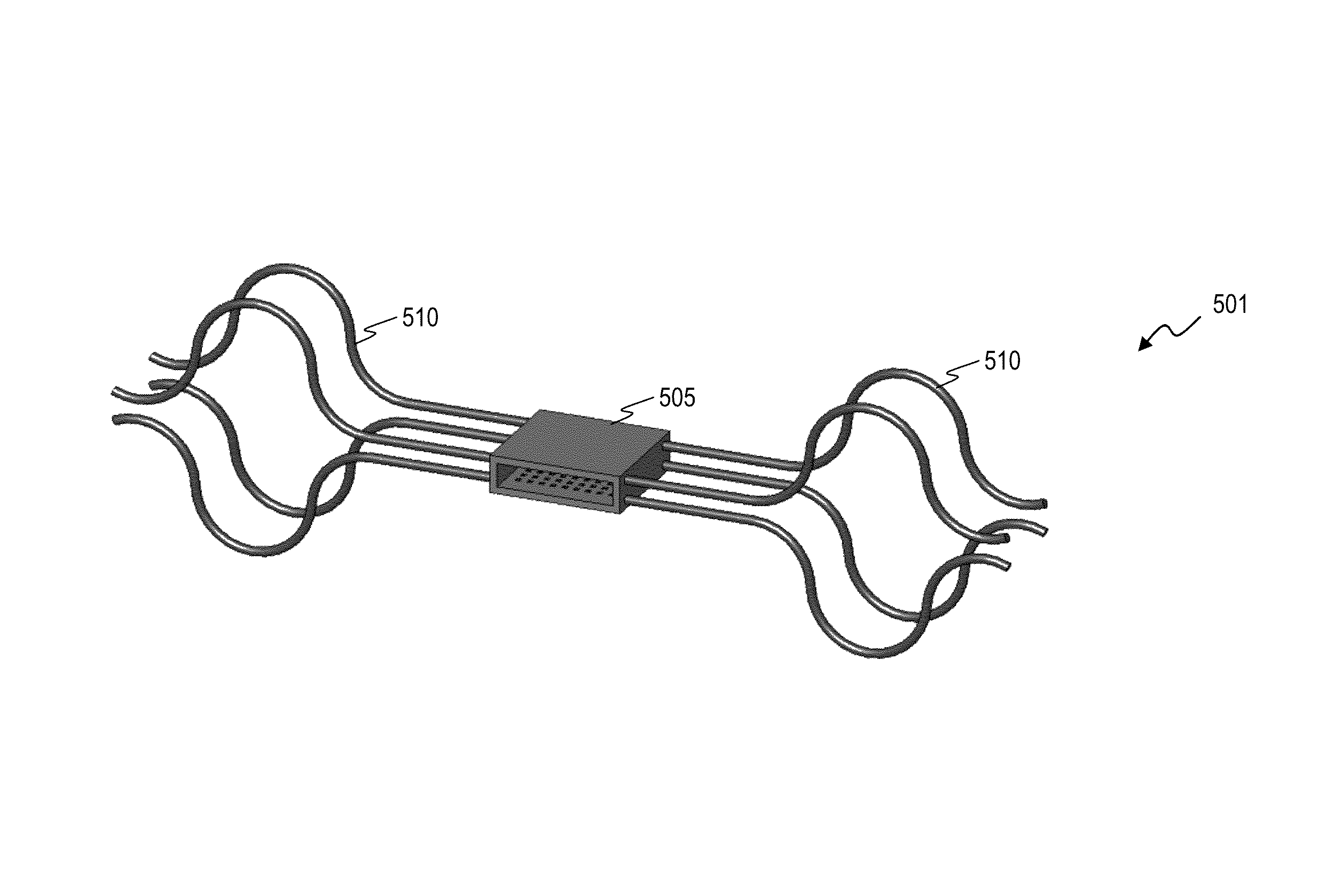
[0073]In some embodiments, the present invention provides an apparatus that includes an infrared-light nerve stimulation-plus-therapeutic-heat (INS-plus-TH) device configured to be implanted in an animal, wherein the INS-plus-TH device includes: a plurality of light sources that output infrared-light signals that are efficacious for nerve stimulation, wherein the light sources generate heat; a controller operatively coupled to control the plurality of light sources; and a plurality of thermally conductive material extensions that lead away from the INS-plus-TH device and spread the heat into surrounding tissue of the animal and away from at least one of the group consisting of the light sources and the controller.

Problems solved by technology

Chronic or recurrent pain affects 20-25% of the U.S. population, and it leads to approximately $100 billion in health care costs each year.
The rule of thumb for leading pain researchers is that almost every major pain treatment creates about a 50% reduction in pain for 30-40% of patients (there is generally no good way to identify who will respond to a given treatment).
Many drugs, particularly opioids, carry significant side effects and can become addictive.
While these electrical-signal-stimulation devices can be effective, they often lack the specificity to target the specific neurons responsible for pain without also activating other sensory or motor neurons as a side effect (because electrical current spreads in the body, most if not all neuromodulation devices wind up stimulating other nerves in the area besides the intended target (e.g. causing tremors or unintended sensations)).

Method used


Image

  • Apparatus and method for managing chronic pain with infrared light sources and heat
  • Apparatus and method for managing chronic pain with infrared light sources and heat
  • Apparatus and method for managing chronic pain with infrared light sources and heat

Examples


Embodiment Construction

[0126]Although the following detailed description contains many specifics for the purpose of illustration, a person of ordinary skill in the art will appreciate that many variations and alterations to the following details are within the scope of the invention. Accordingly, the following preferred embodiments of the invention are set forth without any loss of generality to, and without imposing limitations upon the claimed invention.

[0127]In the following detailed description of the preferred embodiments, reference is made to the accompanying drawings that form a part hereof, and in which are shown by way of illustration specific embodiments in which the invention may be practiced. It is understood that other embodiments may be utilized and structural changes may be made without departing from the scope of the present invention.

[0128]The leading digit(s) of reference numbers appearing in the Figures generally corresponds to the Figure number in which that component is first introduc...


PUM


Abstract

Method and apparatus for infrared-light nerve stimulation-plus-therapeutic-heat (INS-plus-TH) that includes providing a plurality of light sources; providing a plurality of thermally conductive extensions configured to transfer heat generated by the plurality of light sources away from the plurality of light sources; emitting a plurality of infrared-light nerve-stimulation signals toward neural tissue of an animal from the plurality of light sources, wherein the emitted infrared-light nerve-stimulation signals are configured to generate action potentials in the neural tissue, and wherein the emitting of the plurality of infrared-light nerve-stimulation signals includes generating heat; controlling the emitting of the plurality of infrared-light nerve-stimulation signals to generate action potentials in the neural tissue; and transferring the heat generated by the plurality of light sources during the emitting of the plurality of infrared-light nerve-stimulation signals away from the plurality of light sources and into surrounding tissue of the animal using the plurality of thermally conductive extensions.

Description

CROSS-REFERENCE TO RELATED APPLICATIONS[0001]This invention is related to:[0002]U.S. Pat. No. 7,736,382 titled “APPARATUS FOR OPTICAL STIMULATION OF NERVES AND OTHER ANIMAL TISSUE” that issued Jun. 15, 2010 to James S. Webb et al.,[0003]U.S. Pat. No. 7,883,536 titled “HYBRID OPTICAL-ELECTRICAL PROBES” that issued Feb. 8, 2011 to Mark P. Bendett et al.,[0004]U.S. patent application Ser. No. 11 / 536,639 filed Sep. 28, 2006 by James S. Webb et al., titled “MINIATURE APPARATUS AND METHOD FOR OPTICAL STIMULATION OF NERVES AND OTHER ANIMAL TISSUE” (which issued as U.S. Pat. No. 7,988,688 on Aug. 2, 2011),[0005]U.S. patent application Ser. No. 11 / 948,912 filed Nov. 30, 2007 by James S. Webb et al., titled “APPARATUS AND METHOD FOR CHARACTERIZING OPTICAL SOURCES USED WITH HUMAN AND ANIMAL TISSUES”,[0006]U.S. patent application Ser. No. 11 / 536,642 filed Sep. 28, 2006 by Mark P. Bendett et al., titled “APPARATUS AND METHOD FOR STIMULATION OF NERVES AND AUTOMATED CONTROL OF SURGICAL INSTRUMENTS...

Claims


Application Information

Patent Timeline
Patent Type & Authority Patents(United States)
IPC IPC(8): A61N5/06
CPCA61N5/0601A61N5/0622A61N5/0625A61N1/0529A61N1/0551A61N1/36017A61N1/3605A61N1/36071A61N2005/0659A61N5/067A61N1/05A61N1/056
Inventor OWEN, JAMES M.KELLER, MATTHEW D.YUAN, SHUMING
Owner NERVESENSE LTD
Why Eureka
Try Eureka