Hybrid working vehicle

a working vehicle and hybrid technology, applied in the direction of propulsion parts, jet propulsion mounting, process and machine control, etc., can solve the problems of increasing the number of parts and costs, inhibiting the minimization of the vehicle, increasing torque and energy loss, etc., to achieve the effect of improving the turning performance of the vehicl

Active Publication Date: 2015-03-31
KANZAKI KOKYUKOKI MFG
View PDF14 Cites 11 Cited by
  • Summary
  • Abstract
  • Description
  • Claims
  • Application Information

AI Technical Summary

Benefits of technology

[0008]An object of the invention is to provide a hybrid working vehicle which can steplessly speed-shift during traveling or working by use of engine power and can combine the electric motor power and the engine power so as to effectively assist the engine torque, thereby reducing energy loss and ensuring compactness and economy of the vehicle.

Problems solved by technology

Therefore, an electric motor for driving rear wheels, an electric motor for driving front wheels and an electric motor for PTO driving are necessary, thereby increasing the number of parts and costs and inhibiting minimization of the vehicle.
In other words, since the electric motor power cannot be combined with the engine power, the function of the electric motor for assisting the engine in torque cannot be effectively exerted during starting or acceleration of the vehicle by use of the engine power or during high loaded work of the working implement by use of the engine power, thereby increasing loss of torque and energy.
In this way, the problem of the conventional hybrid working vehicle is its insufficient effect in energy saving and in leveling the engine load.

Method used


Image

  • Hybrid working vehicle
  • Hybrid working vehicle
  • Hybrid working vehicle

Examples


Embodiment Construction

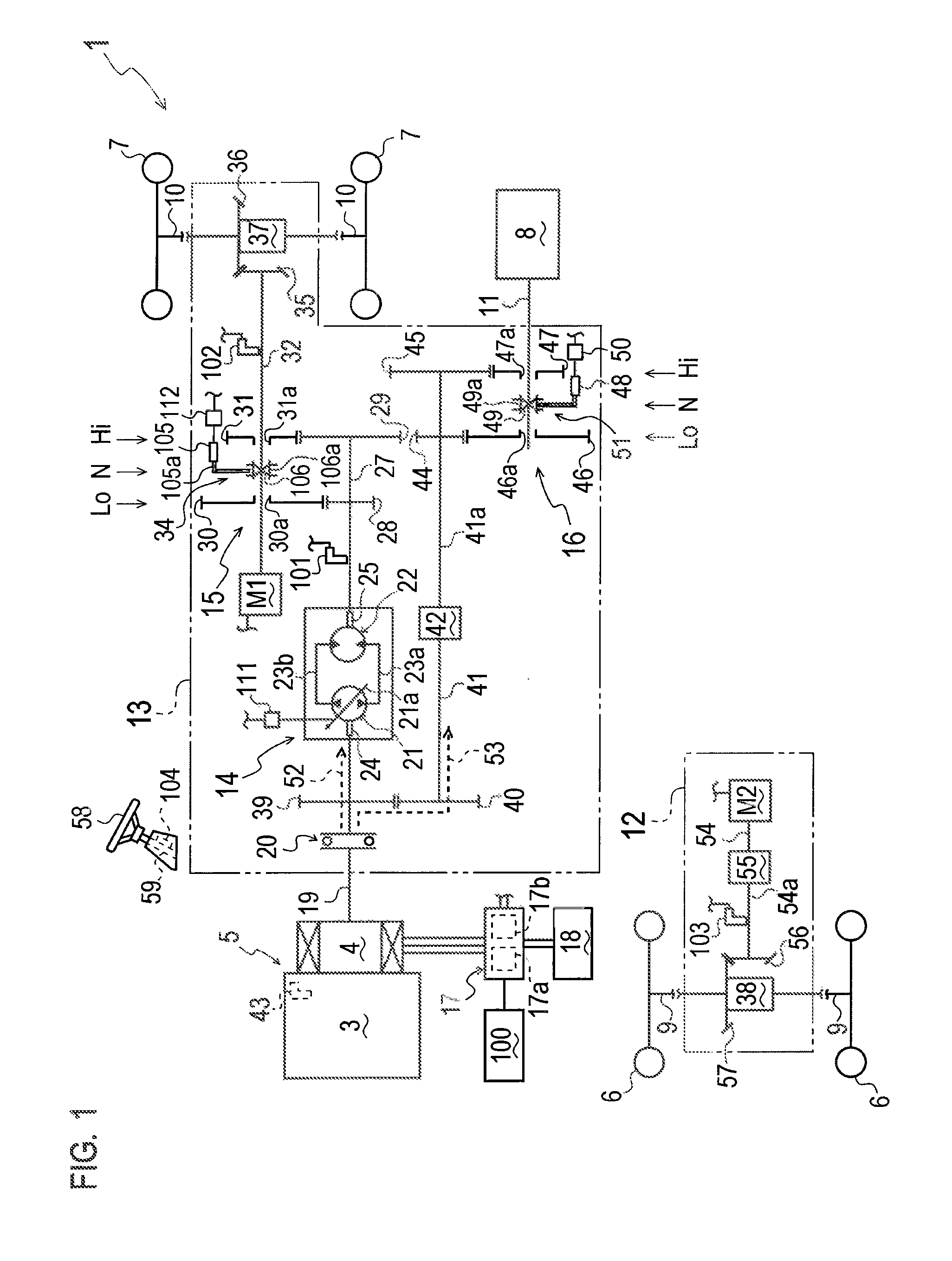
[0036]Referring to FIG. 1, a general construction of a hybrid working vehicle 1 will be described. Vehicle 1 is a four-wheel drive tractor that is equipped with a power unit 5 including an engine (internal combustion engine) 3 and a motor generator 4. Vehicle 1 is equipped at a front portion thereof with a front transaxle 12, and is equipped at a rear portion thereof with a rear transaxle 13. Front transaxle 12 supports right and left front axles 9, and right and left front drive wheels 6 are provided on distal ends of respective front axes 9. Rear transaxle 13 supports right and left rear axles 10, and right and left rear drive wheels 7 are provided on distal ends of respective rear axles 10. Rear transaxle 13 also supports a rearwardly projecting PTO shaft 11 for driving a working implement 8, e.g., a rotary cultivator, connected to a rear end of PTO shaft 11.

[0037]Rear transaxle 13 includes a first electric motor M1 for driving rear axles 10. Front transaxle 12 includes a second ...


PUM


Abstract

A hybrid working vehicle comprises an engine, a drive wheel, a power take-off (PTO) shaft, and a power transmission system for transmitting power from the engine to the drive wheel and the PTO shaft. The power transmission system is bifurcated at a bifurcating point into a traveling drive train for driving the drive wheel and a PTO drive train for driving the PTO shaft. A continuously variable transmission is provided on the traveling drive train, and a motor generator is provided on the power transmission system between the engine and the bifurcating point. The motor generator functions as a generator by power of the engine and functions as an electric motor for driving the power transmission system. The hybrid working vehicle includes a controller for controlling an output rotary speed of the motor generator functioning as the electric motor.

Description

BACKGROUND OF THE INVENTION[0001]1. Technical Field[0002]The present invention relates to a hybrid working vehicle having an engine and an electric motor for driving a drive wheel and a power take-off (PTO) shaft.[0003]2. Related Art[0004]Recently, as disclosed by JP 2007-269072 A, a hybrid drive system including an engine, a generator driven by the engine, and electric motors driven by electric power generated by the generator is used by working vehicles, e.g., construction machines and agricultural machines, as well as motorcars. A working vehicle using this hybrid drive system selects either the engine power or the electric motor power so as to drive front and rear drive wheels and its PTO shaft, thereby achieving various driving modes in travel of the vehicle and in work by drive of the PTO shaft.[0005]In this regard, the electric motors can change their output rotary speeds steplessly (continuously). In other words, the output rotary speeds of the electric motors do not change ...

Claims


Application Information

Patent Timeline
Patent Type & Authority Patents(United States)
IPC IPC(8): B60L11/00B60K6/485B60W10/103B60W10/30B60W20/00B60W30/188
CPCB60K6/485B60W10/103B60W10/30B60W20/00B60W30/1888Y02T10/6226B60K6/442B60K6/52B60K6/543B60K17/28B60W10/08B60Y2200/221B60Y2200/92Y02T10/62B60W10/10B60K6/383B60W20/40
Inventor ISHII, NORIHIRO
Owner KANZAKI KOKYUKOKI MFG
Why Eureka
Try Eureka