Crate assembly jig system, assembly, and method

Inactive Publication Date: 2015-04-07
INGRAM MICHAEL D
View PDF19 Cites 5 Cited by
  • Summary
  • Abstract
  • Description
  • Claims
  • Application Information

AI Technical Summary

Benefits of technology

The present invention is a jig assembly designed to prevent damage to crate-bound materials during assembly. It addresses the issue of misaligned fasteners that can damage the crate materials during assembly. The jig assembly includes first and second fastener-aligning slots or channels and first and second magnet-positioning bores. The slots and bores are located adjacent to the fastener-engaging end, which has a planar frontal surface parallel to the board-engaging surface. The slots or channels are formed in the surface intermediate the end-to-end width. The first and second magnets are received in the magnet-receiving bores at a distance from the surface so as to attract ferrous or magnetically attractable material positioned at the slots or channels. The technical effect of this invention is that it helps prevent inadvertent damage to crate-bound materials during assembly.

Problems solved by technology

During assembly of crate assemblies axial fasteners often become misaligned, their axes becoming oriented in directions that are non-parallel to board surfacing, and in some cases may damage the crate bound materials.

Method used


Image

  • Crate assembly jig system, assembly, and method
  • Crate assembly jig system, assembly, and method
  • Crate assembly jig system, assembly, and method

Examples


Embodiment Construction

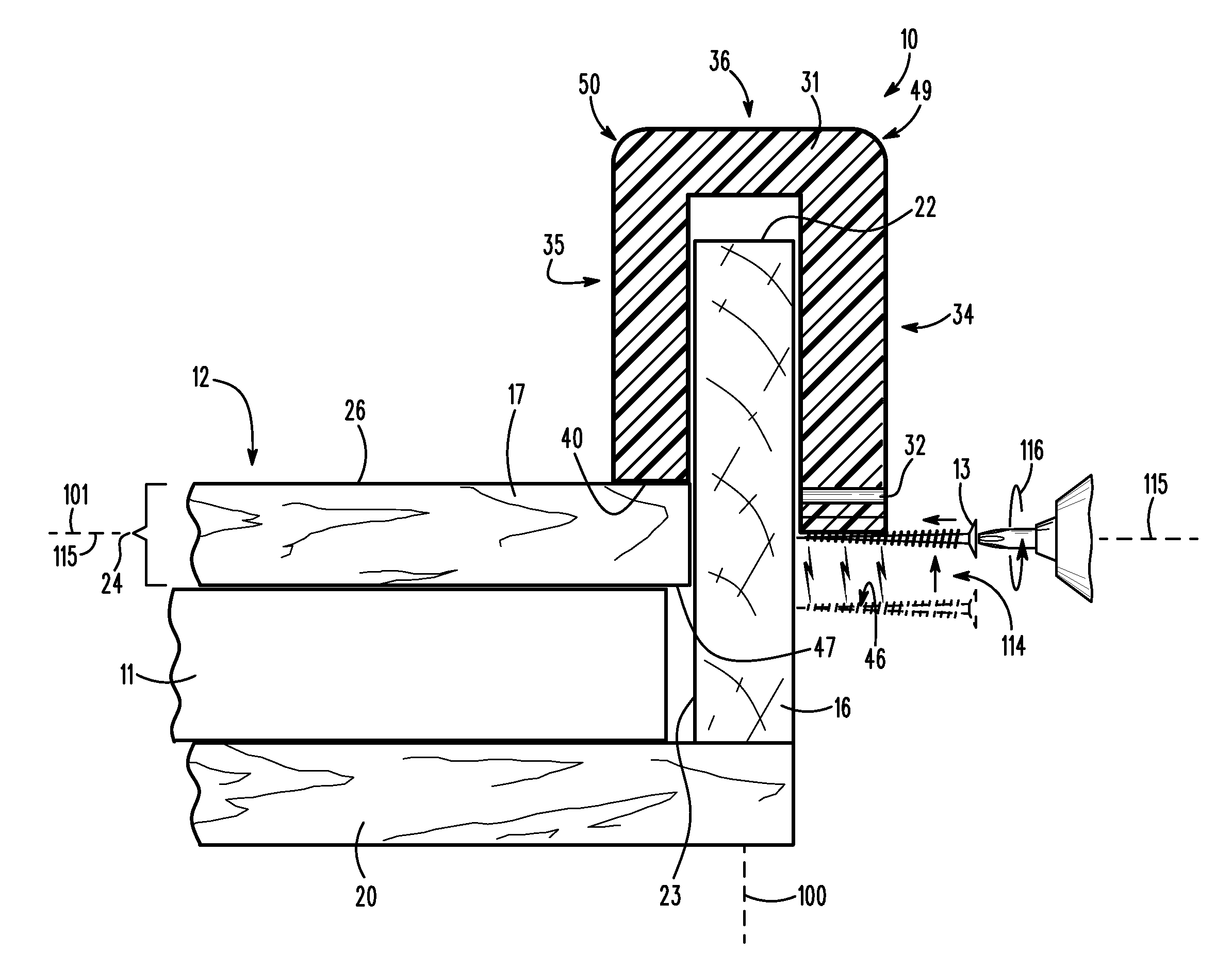
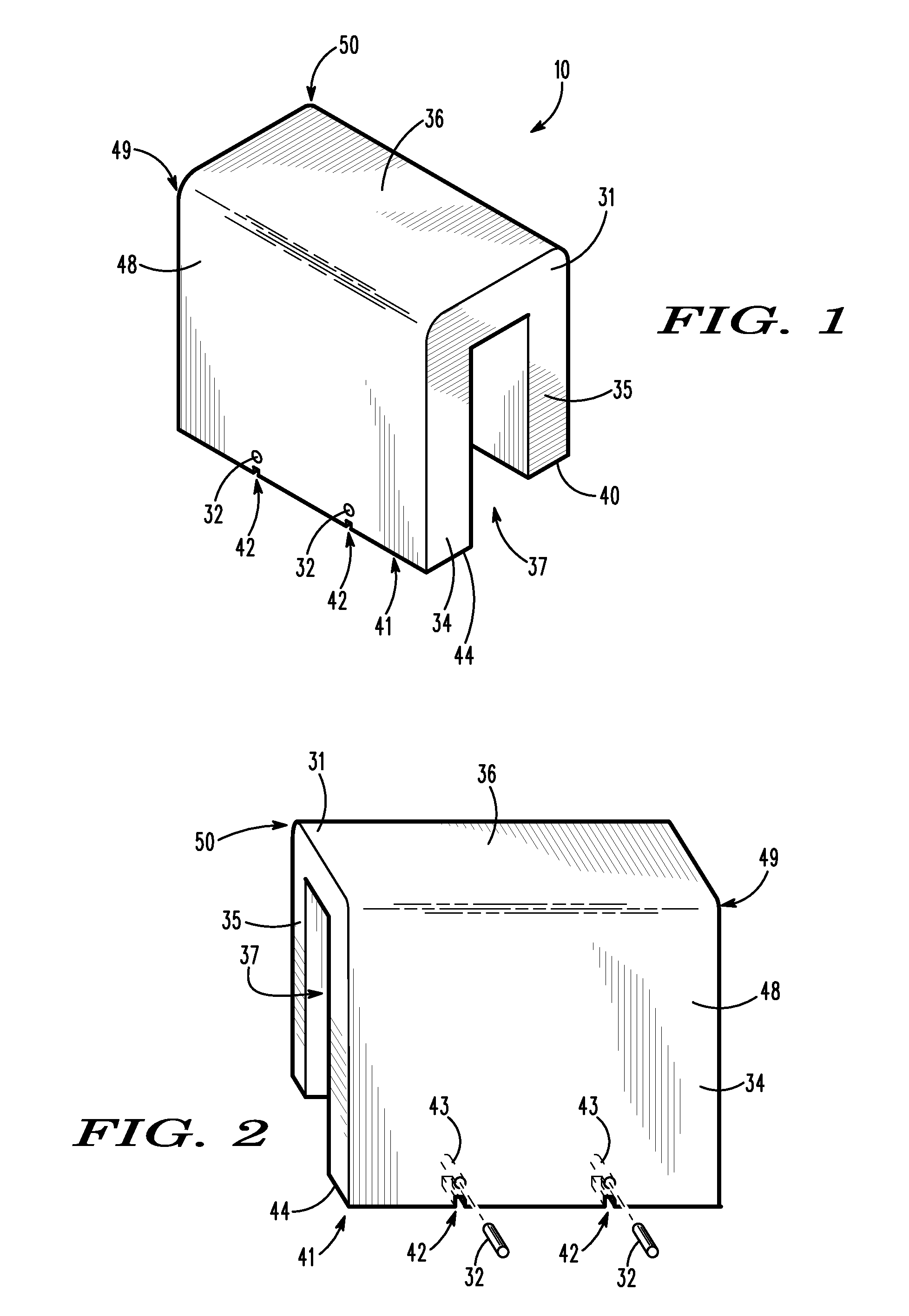
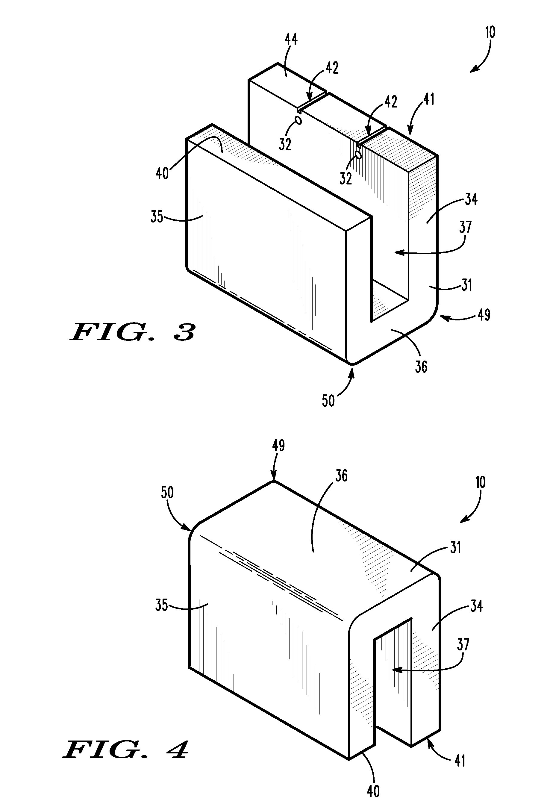
[0043]Referring now to the drawings with more specificity, the preferred embodiment of the present invention provides a jig assembly as at 10 for preventing inadvertent damage to crate-bound materials during crate assembly. Fine works of art as generically depicted at 11 are often shipped via a crate assembly specifically tailored to meet the specifications of the artwork 11. For example, when a framed artistic work is shipped in commerce, the artwork 11 will very often be packaged within a crate assembly as at 12.

[0044]To ensure that the artwork 11 or similar other precious cargo are secure within the shipping crate assembly 12, the shipping crate assembly 12 must be tailored so as to package the artwork 11 or similar other precious cargo within precise specifications. The precise specifications are often critical so as to prevent shifting of the artwork 11 relative to the crate assembly 12 during shipment. From a comparative inspection of FIGS. 11-13, for example, the reader will ...


PUM

PropertyMeasurementUnit
Lengthaaaaaaaaaa

Abstract

A jig assembly is used to manufacture shipping crates essentially functioning to prevent damage to crate-bound material. The jig assembly includes a jig form and magnets. The jig form has a front portion, a rear portion, and a top portion extending between and connecting the front and rear portions. The front portion is parallel to the rear portion such that the front, rear, and top portions together define a board-receiving channel. The front portion has a pair of fastener-aligning slots and a pair of magnet-positioning bores for receiving and positioning the magnets. Fasteners are positioned by the slots and magnets. The board-receiving channel receives a first board of a crate assembly. The properly aligned fasteners may then be driven through the first board into a second board of the crate assembly so as to prevent damage to the crate-bound material. Certain jigging methodology is further supported by the jig assembly.

Description

BACKGROUND OF THE INVENTION[0001]1. Field of the Invention[0002]The present invention relates generally to a jig device or assembly for use in the manufacture of crate assemblies. More particularly, the present invention relates to a jig device or assembly for maintaining the proper alignment of certain fasteners during the assembly of crates for shipping precious cargo.[0003]2. Brief Description of the Prior Art[0004]Jigs or templates are well known in the metalworking and woodworking arts, having been known long before the industrial age. There are many types of jigs, and each one is typically custom-tailored to perform a specific function. Many jigs are created because there is a necessity to do so by the tradesmen, while others are developed to increase productivity, to perform repetitious activities, and to perform a specific function more precisely.[0005]Essentially, a jig is a type of tool used to control the location and / or motion of another tool. A jig's primary purpose is ...

Claims


Application Information

Patent Timeline
IPC IPC(8): B23Q3/00B25G3/00B25D1/00B23P19/10B25B11/00
CPCB25B11/002B23P19/10B25B23/12Y10T403/1616Y10T29/49895
Inventor INGRAM, MICHAEL D.
Owner INGRAM MICHAEL D
Why Eureka
Try Eureka