Ultrasonic flow sensor for use in a fluid medium

a technology of ultrasonic flow sensor and fluid medium, which is applied in the direction of volume/mass flow measurement, measurement devices, instruments, etc., can solve the problem of providing an unambiguous ultrasonic transmission path

Inactive Publication Date: 2015-04-07
ROBERT BOSCH GMBH
View PDF23 Cites 0 Cited by
  • Summary
  • Abstract
  • Description
  • Claims
  • Application Information

AI Technical Summary

Benefits of technology

[0009]In other words, this means that, in contrast to the W-shaped pattern of the system illustrated in DE 39 41 544 A1, within the scope of the exemplary embodiments and / or exemplary methods of the present invention a V-shaped pattern of the ultrasonic signals between the ultrasonic converters is provided as a particular propagation path. The ultrasonic converters may also be installed in such a way that they are slightly tilted with respect to the ideal V-shaped pattern, as the result of which, for example, a stop against beam drifts during flow may be provided, and / or multiple reflections between the two converter surfaces may be reduced.
[0022]As described above, in addition to the longitudinal offset with respect to the flow direction, the ultrasonic converters may also be offset relative to one another transversely with respect to the flow of the fluid medium. It is thus possible, for example, to prevent flow irregularities, produced by an ultrasonic converter situated upstream, from influencing an ultrasonic converter situated downstream.
[0024]In particular, the reflection barrier may be configured in such a way that it includes a lamella having the following properties: First of all, the lamella has a main direction of extension having a nonvanishing vector component transverse to the direct connecting line between the ultrasonic converters, so that sound waves from one ultrasonic converter, via a first reflection on the reflection surface, do not reach the other converter to a greater degree via one or multiple reflections on the deflection device and a second reflection on the reflection surface, but instead are back-reflected or tend to be reflected away laterally. Alternatively or additionally, due to the configuration of the ultrasonic converter transversely offset to the flow direction, the lamella may be situated parallel or essentially parallel to the flow direction, so that the lamella does not disturb the course of the flow. As a result of this configuration of a main structure of the deflection device in the flow direction, the appropriate structural depth may be selected to be correspondingly greater without disturbing the course of the flow, so that a proper barrier for the W-shaped sound pattern may be implemented.
[0027]The proposed ultrasonic flow sensor has several advantages over known ultrasonic flow sensors. Thus, in particular an unambiguous ultrasonic transmission path may be ensured with extensive suppression of parasitic ultrasonic paths. As described above, the ultrasonic flow sensor may be configured in particular with two ultrasonic converters which are offset in the flow to be measured and which exchange ultrasonic signals via the reflection surface. The orientation of the reflection surface may be specified in particular by its main normal vector Nh in the reflection region. As described above, the measuring tube surface may be divided into the three surface regions, defined above, between the ultrasonic converters in the direction of the connecting line between the ultrasonic converters, and the extensions of these surface regions longitudinally and transversely with respect to this connecting line are at least approximately one-third of length L of the connecting line.
[0030]In contrast, as a result of the exemplary embodiments and / or exemplary methods of the present invention the measurement repetition rate may be brought into a range, without additional measuring errors, that is necessary for sufficient sampling of pulsing flows, for example in the intake, fresh air, or exhaust gas region of internal combustion engines. Compared to the device of DE 39 41 544 A1, the advantage lies in particular in the primary V-shaped sound path, which requires only a single reflection.

Problems solved by technology

However, the ultrasonic flow sensor based on a reflection principle provides an unambiguous ultrasonic transmission path.

Method used


Image

  • Ultrasonic flow sensor for use in a fluid medium
  • Ultrasonic flow sensor for use in a fluid medium
  • Ultrasonic flow sensor for use in a fluid medium

Examples


Embodiment Construction

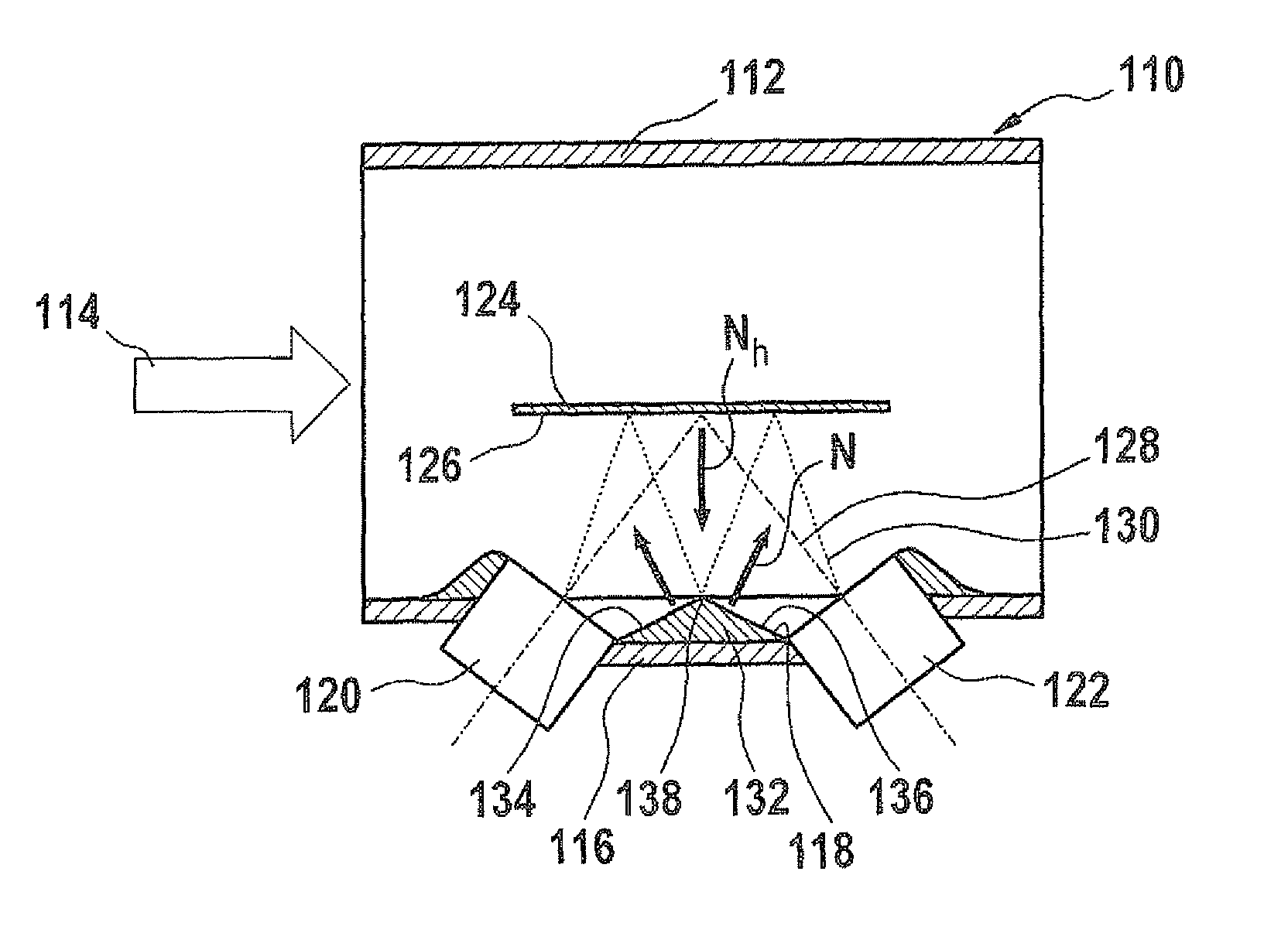
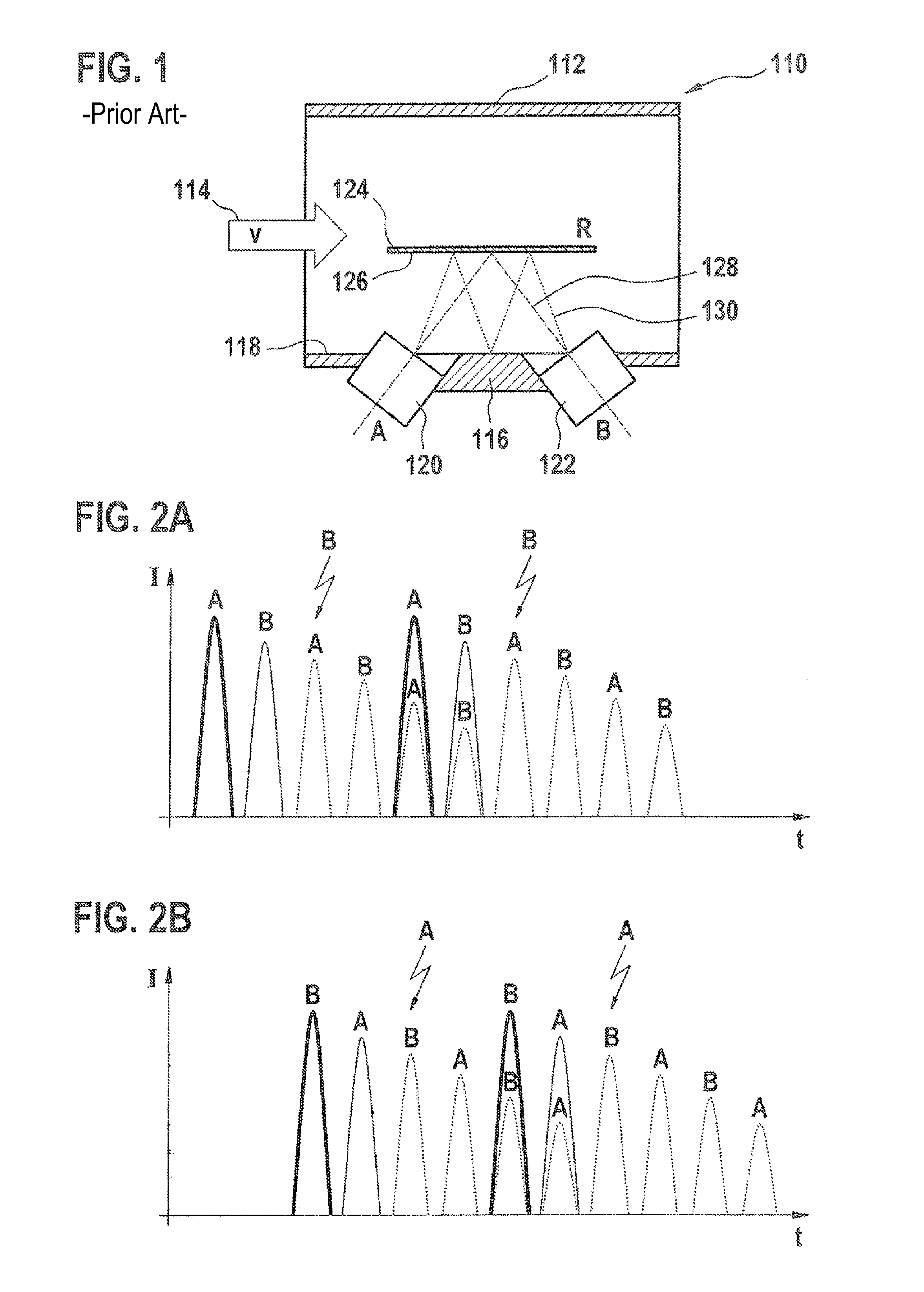
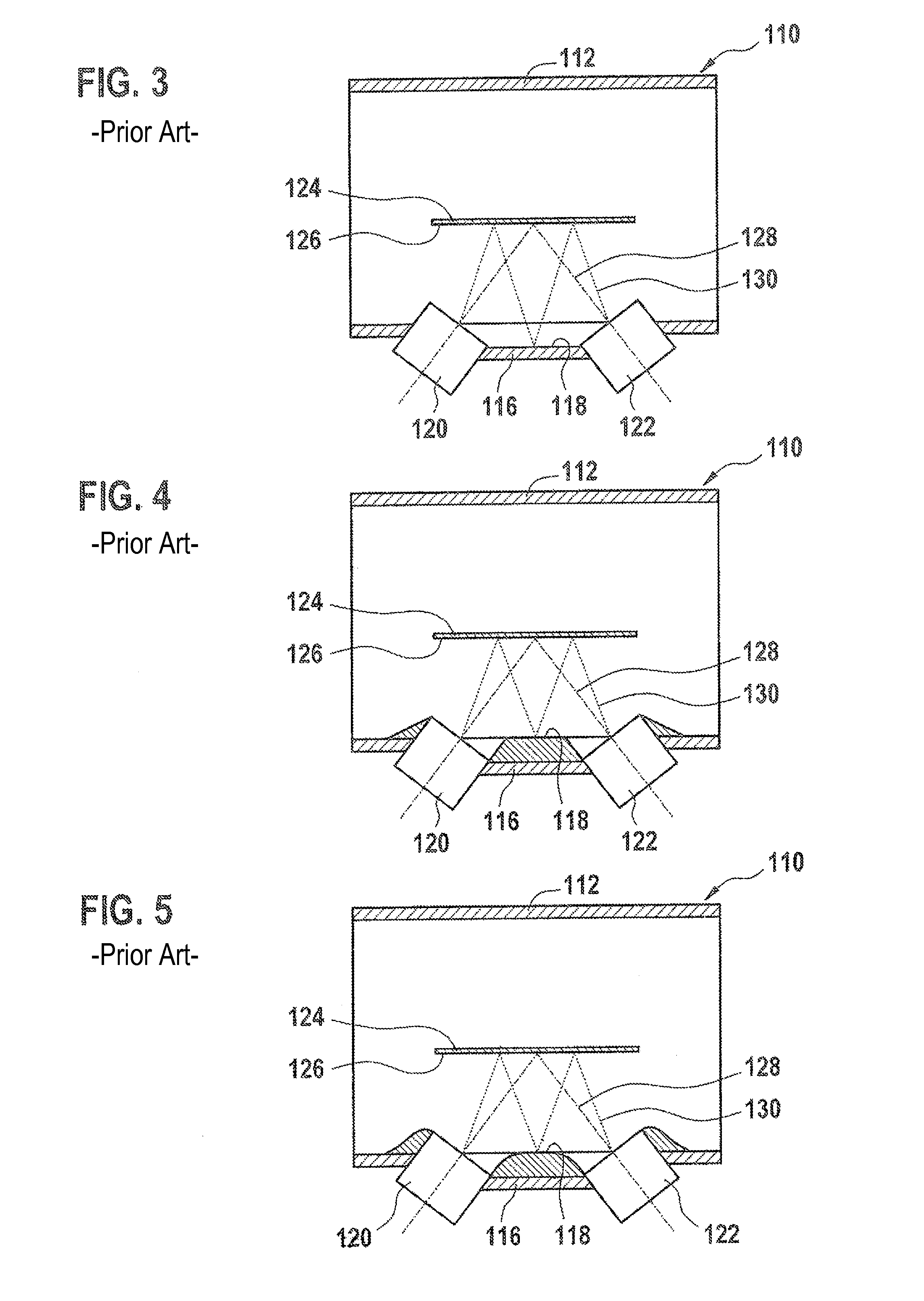
[0039]FIG. 1 shows a known ultrasonic flow sensor 110 as the starting point for the present patent application. This ultrasonic flow sensor has a flow tube 112, through which a fluid medium, for example an exhaust gas of an internal combustion engine and / or an air mass in an intake system of an internal combustion engine (for example, also after compression by a turbocharger), flows in a flow direction 114 at a velocity denoted by reference character v in FIG. 1. Flow tube 112 has a measuring tube 116 which, for example, may form a section of flow tube 112, or which may also be formed by a housing, and which is mounted as a plug-in sensor in flow tube 112. Two ultrasonic converters 120, 122 are offset relative to one another, longitudinally with respect to flow direction 114, in a measuring tube surface 118 of measuring tube 116.

[0040]These ultrasonic converters 120, 122 are also denoted by letters A and B in FIG. 1. Ultrasonic converters 120, 122 exchange ultrasonic waves via a ref...


PUM


Abstract

An ultrasonic flow sensor for use in a fluid medium is described. The ultrasonic flow sensor includes at least two ultrasonic converters which are situated in a flow tube offset relative to one another, longitudinally with respect to a flow of the fluid medium. The ultrasonic flow sensor also includes a reflection surface, the ultrasonic converters being set up to exchange ultrasonic signals via simple reflection on the reflection surface. In addition, a deflection device is provided between the ultrasonic converters which is set up to essentially suppress parasitic ultrasonic signals, which are reflected from the reflection surface and which strike the deflection device, by deflection away from the ultrasonic converters.

Description

FIELD OF THE INVENTION[0001]The present invention relates to an ultrasonic flow sensor for use in a fluid mediumBACKGROUND INFORMATION[0002]Numerous flow sensors are believed to be understood from the related art for detecting the flow of a fluid medium. These types of ultrasonic flow sensors are understood to detect, for example, a mass flow, a volume flow, or a velocity of the fluid medium, for example in a flow tube. Two or more ultrasonic converters are usually used, which are situated in the flow offset relative to one another, longitudinally with respect to the flow of the fluid medium, and which are able to exchange ultrasonic signals. Based on differences in the propagation times of the ultrasonic signals having a component in the flow direction and having a component against the flow direction, the flow rate and / or other variables which characterize the flow may be deduced.[0003]One example of this type of ultrasonic flow sensor (which within the scope of the exemplary embo...

Claims


Application Information

Patent Timeline
Patent Type & Authority Patents(United States)
IPC IPC(8): G01F1/66
CPCG01F1/662
Inventor LANG, TOBIAS
Owner ROBERT BOSCH GMBH
Why Eureka
Try Eureka