Glass cutting machine, glass cutter, and glass cutting method
a cutting machine and glass technology, applied in the direction of manufacturing tools, transportation and packaging, paper/cardboard containers, etc., can solve the problems of large risk, insufficient treatment of problems, generation of defective parts, etc., to improve yield, prevent riding, and form vertical cracks stably on the glass surface
- Summary
- Abstract
- Description
- Claims
- Application Information
AI Technical Summary
Benefits of technology
Problems solved by technology
Method used
Image
Examples
first embodiment
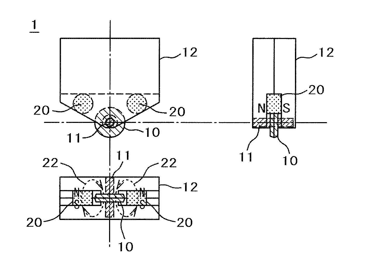
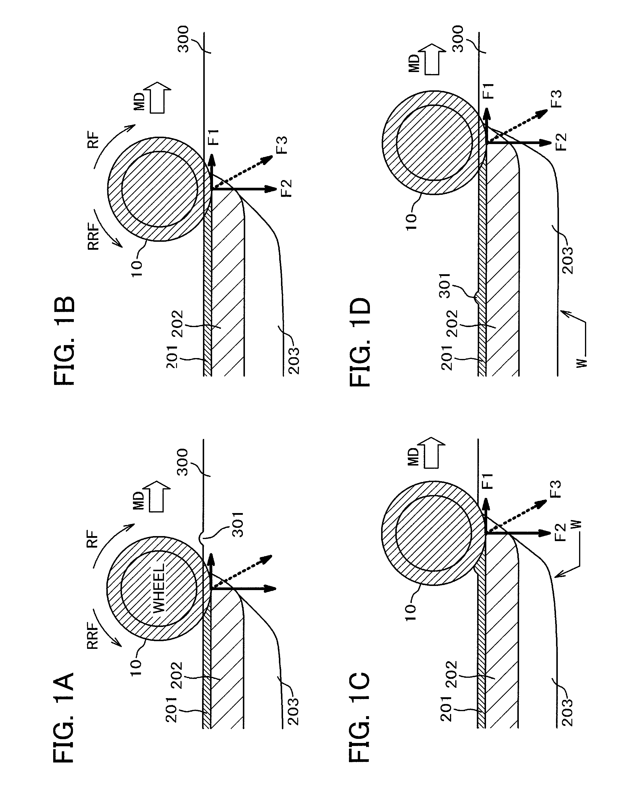
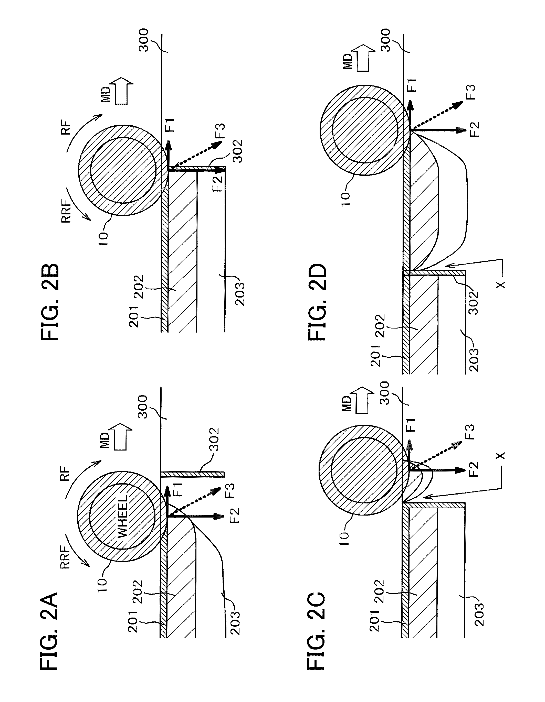
[0059]FIG. 3 shows the glass cutter 1 of the first embodiment. As shown, the wheel 10 is supported by a wheel pin 11 and the wheel pin 11 is supported by a holder 12. The wheel 10 is formed of sintered diamond added to by Co which is a magnetic material, so that the wheel 10 as a whole is a magnetic body. The holder 12 is formed of tool steel which is an ultrahard material, so that it is a magnetic body. Two magnets 20 are provided on outsides of the holder 12. The magnets 20 generate a magnetic field of a prescribed magnetic flux density and, by having the magnetic field crossed by the wheel 10, applies a force to press the wheel 10 against a side of the holder 12. Pressing the wheel 10 against a side of the holder 12 generates a force RRF to oppose the rotating force RF of the wheel 10, so that a fracture layer and a crack can be formed in the glass in a stable manner.
[0060]Referring to FIG. 3, the magnets 20 sandwiching the holder 12 are disposed with the north pole of one of the...
second embodiment
[0062]FIG. 4 is a diagram showing a second embodiment of the present invention. The wheel 10, wheel pin 11, holder 12, and magnets 20 shown in FIG. 4 are basically identical with those shown in FIG. 3. In the configuration shown in FIG. 4, the holder 12 and the magnets 20 are surrounded by a magnetic frame 21 with a high magnetic permeability with the magnetic frame 21 providing magnetic paths. In FIG. 4, broken-line arrows shown on the magnetic frame 21 represent a magnetic flux. With magnetic paths formed in the magnetic frame 21, reluctance is reduced, so that the magnetic flux to flow through the wheel 10 becomes larger. This increases the force to oppose rotation of the wheel 10.
[0063]Since the magnetic flux passing through the wheel 10 becomes larger, the eddy current generated by the rotation of the wheel 10 becomes larger, so that the force generated by the eddy current to oppose rotation of the wheel 10 also becomes larger. The magnetic frame 21 is made of, for example, per...
third embodiment
[0064]FIG. 5 is a diagram showing a third embodiment of the present invention. As shown in FIG. 5, the magnets 20 are embedded in a gap inside the holder 12. The magnets 20 of the third embodiment each measure 3 mm in diameter and 1.5 mm in thickness. Even though, the magnets 20 of the third embodiment are smaller than those of the first and second embodiments, the magnets 20 are disposed closer to the wheel 10 in the third embodiment than in the first and second embodiments, so that a magnetic flux required to be crossed by the wheel 10 can be secured. Referring to FIG. 5, the magnetic poles of the magnets 20 are arranged along the thickness direction of the holder 12 with the north and south poles oriented identically between the two magnets. This secures a magnetic flux perpendicular to the side surfaces of the wheel 10.
[0065]In the present embodiment, too, a force to press the wheel 10 against the holder 12 so as to oppose rotation of the wheel 10 can be generated by a magnetic ...
PUM
| Property | Measurement | Unit |
|---|---|---|
| depth | aaaaa | aaaaa |
| diameter | aaaaa | aaaaa |
| thickness | aaaaa | aaaaa |
Abstract
Description
Claims
Application Information
 - R&D
- Intellectual Property
- Life Sciences
- Materials
- Tech Scout
- Unparalleled Data Quality
- Higher Quality Content
- 60% Fewer Hallucinations
Browse by: Latest US Patents, China's latest patents, Technical Efficacy Thesaurus, Application Domain, Technology Topic, Popular Technical Reports.
© 2025 PatSnap. All rights reserved.Legal|Privacy policy|Modern Slavery Act Transparency Statement|Sitemap|About US| Contact US: help@patsnap.com


