Computer-aided bone scan assessment with automated lesion detection and quantitative assessment of bone disease burden changes

a bone scan and automated technology, applied in the field of medical imaging, can solve the problems of not providing a quantitative metric for the comparison of consecutive scans, no prospective study of reported outcomes, and often too time-consuming segmentation programs in clinical settings, so as to reduce the variability of hand-annotated bone scan analysis

Inactive Publication Date: 2015-04-07
RGT UNIV OF CALIFORNIA
View PDF7 Cites 22 Cited by
  • Summary
  • Abstract
  • Description
  • Claims
  • Application Information

AI Technical Summary

Benefits of technology

[0016]In various embodiments, the use of bone scans to monitor treatment effects utilizes accurate segmentation and quantification of lesions within a single scan, as well as the comparison of lesion measurements between consecutive scans. Embodiments provide an automated system that accurately and reproducibly segments and quantifies bone lesions to aid physicians in intrapatient and interpatient comparison.
[0018]Validation shows the system is capable of reducing the variability of hand-annotated bone scan analysis, so that objective, reproducible, and quantitative measurements are consistently obtained which lays a foundation for prospective correlation of individual measures with other clinical and laboratory outcome data.
[0019]Validation shows the system is capable of accurate automated bone scan lesion segmentation (detection of lesion pixels) and capable of providing quantitative measures of lesion burden that may then be used to assess disease status changes in treated and untreated patients.

Problems solved by technology

These techniques have included semi-automated image segmentation programs that are frequently too time-consuming for use in a clinical setting such as those of Erdi et al. and Yin et al.
Although this system showed a good correlation with physician-determined estimates of the probability of bone metastases, the system does not provide a quantitative metric for the comparison of consecutive scans nor a means of assessing treatment outcomes.
Importantly, none of the reported outcomes have been studied prospectively in relation to true measures of patient benefit such as reduction in skeletal-related events or prolongation of life, measures that form the basis for regulatory approvals.
Both BSI and % PABS have undergone initial evaluation as prognostic factors for patients with prostate cancer, but the methods used to calculate these metrics have been time-consuming, requiring extensive manual annotation of bone scans.

Method used


Image

  • Computer-aided bone scan assessment with automated lesion detection and quantitative assessment of bone disease burden changes
  • Computer-aided bone scan assessment with automated lesion detection and quantitative assessment of bone disease burden changes
  • Computer-aided bone scan assessment with automated lesion detection and quantitative assessment of bone disease burden changes

Examples


Embodiment Construction

[0033]The disclosure provided in the following pages describes examples of some embodiments of the invention. The designs, figures, and description are non-limiting examples of the embodiments they disclose. For example, other embodiments of the disclosed device and / or method may or may not include the features described herein. Moreover, disclosed advantages and benefits may apply to only certain embodiments of the invention and should not be used to limit the disclosed invention.

[0034]As used herein, the term “coupled” includes direct and indirect connections. Moreover, where first and second devices are coupled, intervening devices including active devices may be located therebetween.

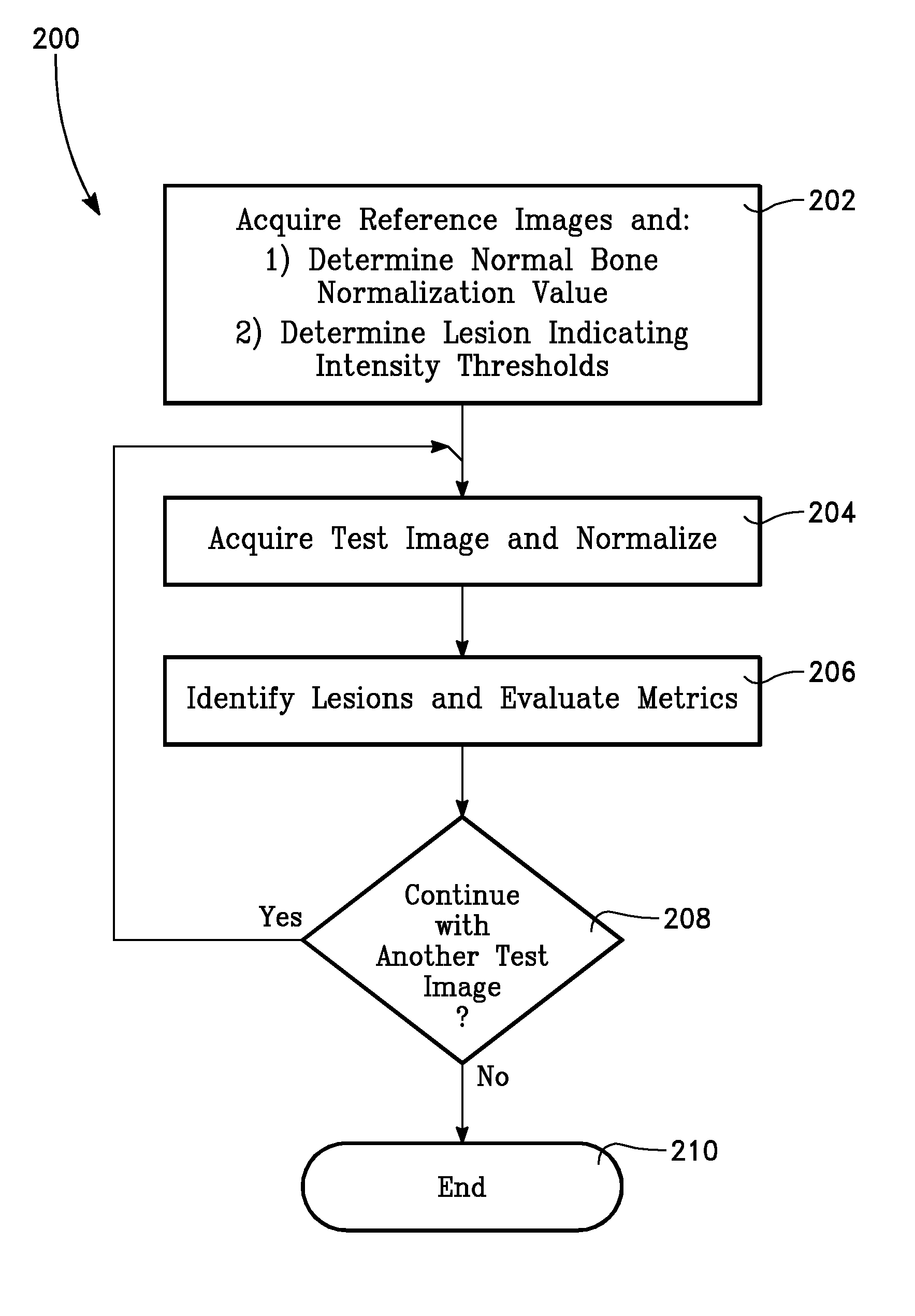
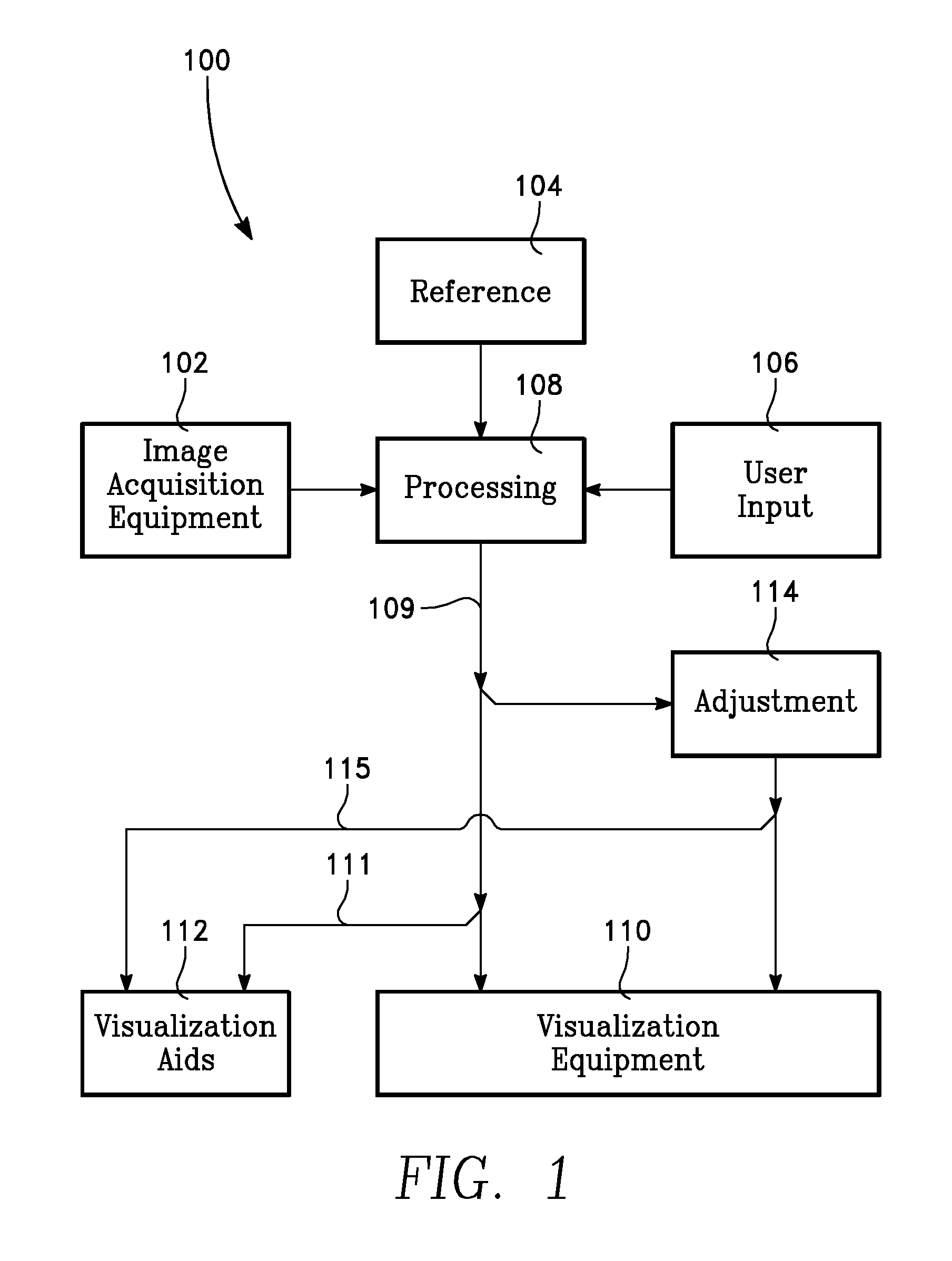
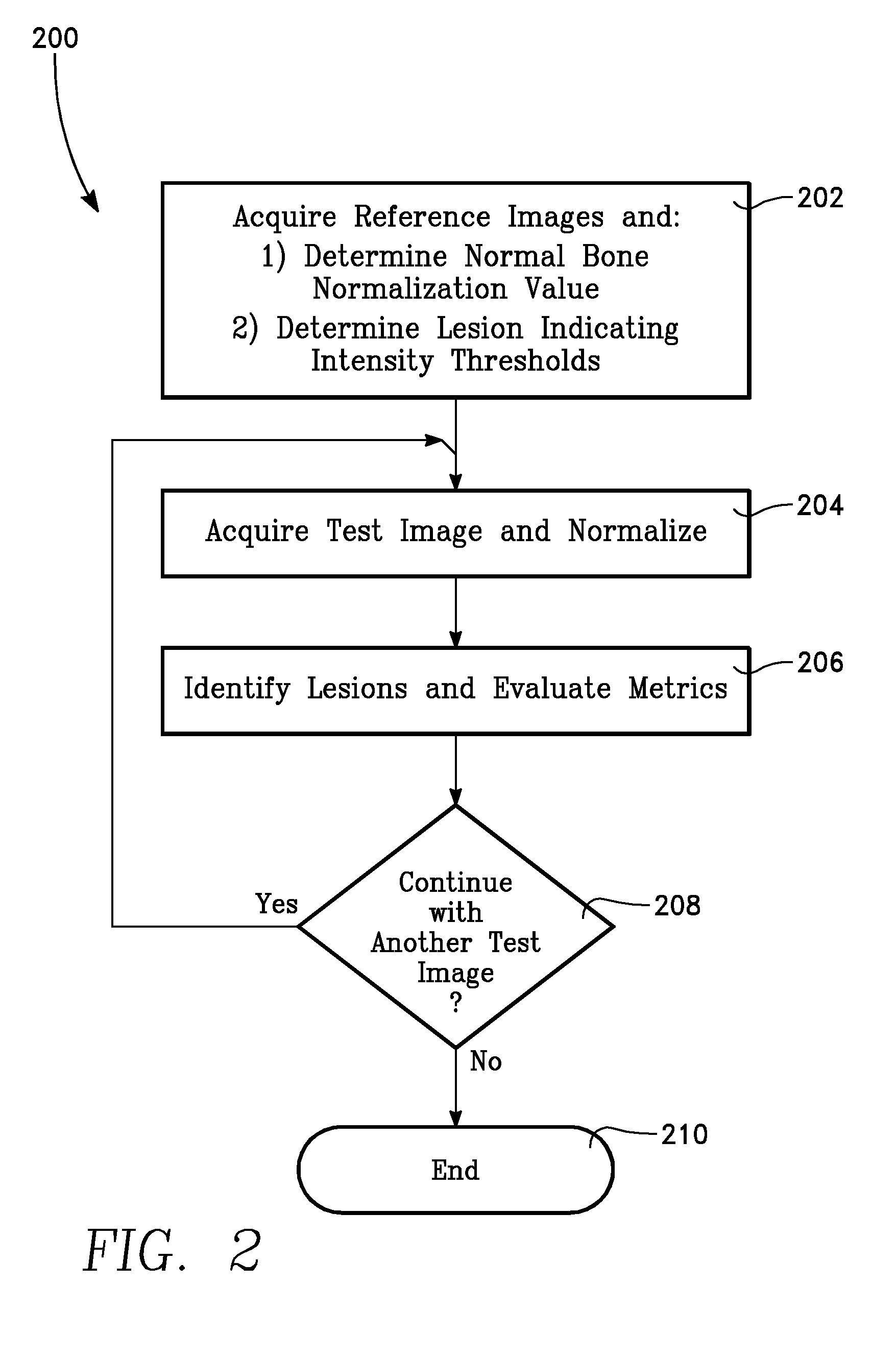
[0035]FIG. 1 shows a computer-aided quantitative bone scan assessment system in accordance with the present invention 100. A processing unit 108 receives image data from image acquisition equipment 102. Data from these and other images, processed or not, is available to the processor via a reference ...


PUM


Abstract

A computer aided bone scan assessment system and method provide automated lesion detection and quantitative assessment of bone disease burden changes.

Description

PRIORITY CLAIM[0001]This application claims the benefit of U.S. Prov. Pat. App. No. 61 / 548,498 filed Oct. 18, 2011 and entitled COMPUTER-AIDED BONE SCAN ASSESSMENT WITH AUTOMATED LESION DETECTION AND QUANTITATIVE ASSESSMENT OF BONE DISEASE BURDEN CHANGES. This application claims the benefit of U.S. Prov. Pat. App. No. 61 / 714,318 filed Oct. 16, 2012 and entitled COMPUTER-AIDED BONE SCAN ASSESSMENT.INCORPORATION BY REFERENCE[0002]This application incorporates by reference in its entirety and for all purposes U.S. Prov. Pat. App. No. 61 / 548,498 filed Oct. 18, 2011 and U.S. Prov. Pat. App. No. 61 / 714,318 filed Oct. 16, 2012.BACKGROUND OF THE INVENTION[0003]1. Field of the Invention[0004]The invention relates to the field of medical imaging. More particularly, the present invention relates to bone scans, bone lesions, and bone disease assessment.[0005]2. Discussion of the Related Art[0006]Bone tumors may originate in bone or they may originate in other sites and spread (metastasize) to t...

Claims


Application Information

Patent Timeline
Patent Type & Authority Patents(United States)
IPC IPC(8): G06K9/00G06T7/00
CPCG06T7/0014G06T7/0081G06T2207/30008G06T2207/10128G06T2207/20148G06T2207/30096G06T7/11G06T7/136
Inventor BROWN, MATTHEW SHERMAN
Owner RGT UNIV OF CALIFORNIA
Why Eureka
Try Eureka