Robotic visual perception system

a visual perception and robot technology, applied in the field of visual perception systems, can solve the problems of thrown off, unable to detect the visual texture, and requiring considerable processing time, and achieve the effect of avoiding the thrown o

Inactive Publication Date: 2015-04-07
HRL LAB
View PDF3 Cites 61 Cited by
  • Summary
  • Abstract
  • Description
  • Claims
  • Application Information

AI Technical Summary

Benefits of technology

[0010]The present invention relates to a visual perception system for determining a position and pose of a three-dimensional object through matching with flexible object templates. The system comprises one or more processors and a memory having instructions such that when the instructions are executed, the one or more processors perform multiple operations. The system receives visual input from a sensor of a robotic controller that senses an object of interest. Rotation-invariant shape features are extracted from the sensed object of interest and a set of object templates. A match is identified between the sensed object of interest and an object template using shape features. The match between the sensed object of interest and the object template is confirmed using appearance features. The sensed object is then identified, and a three-dimensional pose of the sensed object of interest is determined. Based on the determined three-dimensional pose of the sensed object, the robotic controller is used to handle the sensed object of interest.

Problems solved by technology

This generation requires considerable processing time and suffers from object-class ambiguity of neighboring points.
These approaches can operate with only a single camera, but can be thrown off by large changes in lighting or 3D pose.
These approaches are indifferent to visual textures, but can be thrown off by similarly shaped, but differently appearing objects (e.g. a knife versus a screwdriver).
These methods scale to multi-part and articulated objects, but typically rely on appearance features only and are computationally expensive.
Rigid- (and piece-wise rigid-) body transforms (see Literature Reference Nos. 8, 20, and 38), which are commonly used for well-modeled objects, provide precise pose estimates, but cannot handle deformable or previously unseen objects of a known class.
This approach can handle novel objects, but is sensitive to scene lighting and irrelevant background textures.
Deformation mapping (see Literature Reference Nos. 34 and 40) can handle deformable objects, but do not scale well for large number of feature correspondences or handle articulated objects.
However, this approach is restricted to finding tips of objects.
Each of the aforementioned methods exhibit limitations that make them incomplete.

Method used


Image

  • Robotic visual perception system
  • Robotic visual perception system
  • Robotic visual perception system

Examples


Embodiment Construction

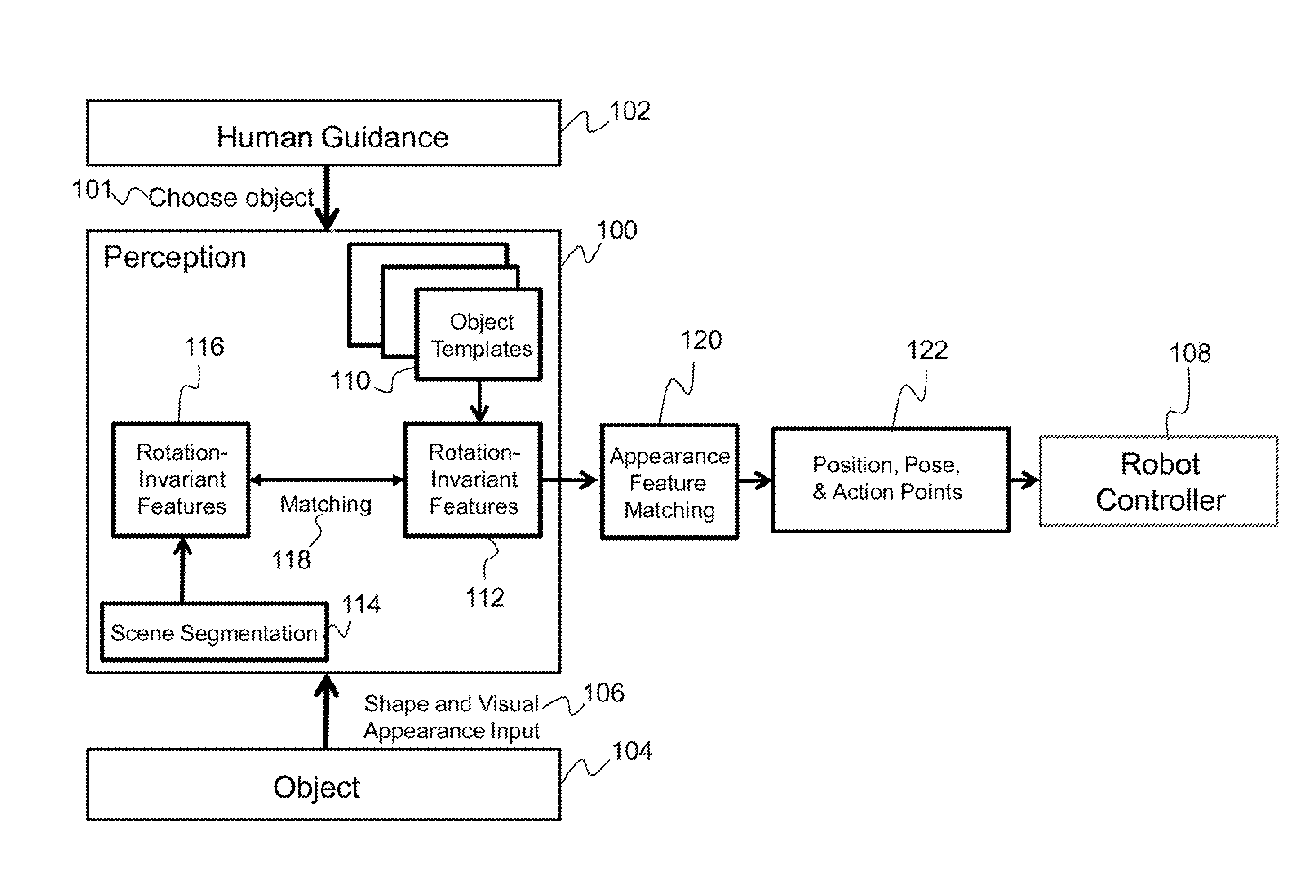
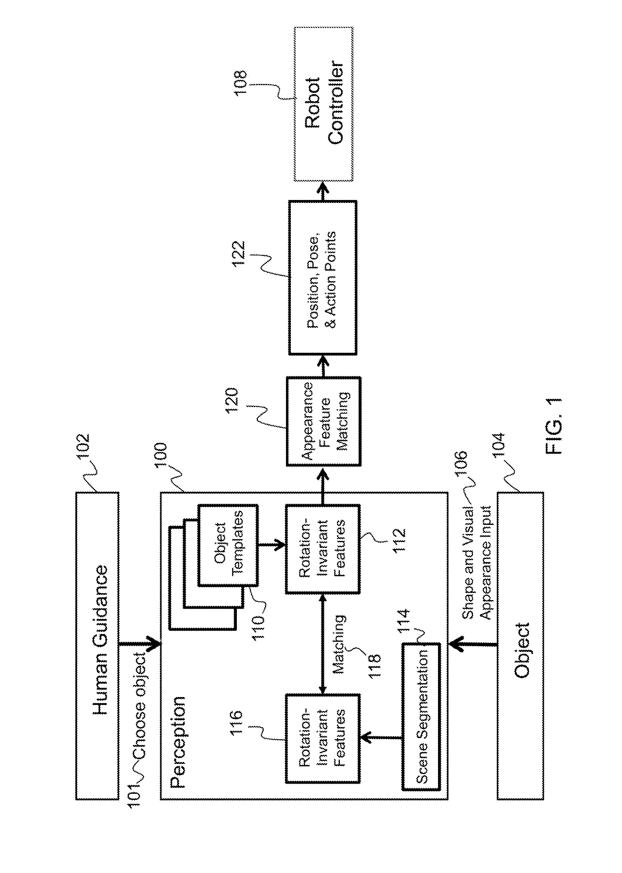
[0030]The present invention relates to a visual perception system for determining a position and pose of a three-dimensional object and, more particularly, to a visual perception system for determining a position and pose of a three-dimensional object through matching with flexible object templates. The following description is presented to enable one of ordinary skill in the art to make and use the invention and to incorporate it in the context of particular applications. Various modifications, as well as a variety of uses, in different applications will be readily apparent to those skilled in the art, and the general principles defined herein may be applied to a wide range of embodiments. Thus, the present invention is not intended to be limited to the embodiments presented, but is to be accorded with the widest scope consistent with the principles and novel features disclosed herein.

[0031]In the following detailed description, numerous specific details are set forth in order to p...


PUM


Abstract

Described is a robotic visual perception system for determining a position and pose of a three-dimensional object. The system receives an external input to select an object of interest. The system also receives visual input from a sensor of a robotic controller that senses the object of interest. Rotation-invariant shape features and appearance are extracted from the sensed object of interest and a set of object templates. A match is identified between the sensed object of interest and an object template using shape features. The match between the sensed object of interest and the object template is confirmed using appearance features. The sensed object is then identified, and a three-dimensional pose of the sensed object of interest is determined. Based on the determined three-dimensional pose of the sensed object, the robotic controller is used to grasp and manipulate the sensed object of interest.

Description

CROSS-REFERENCE TO RELATED APPLICATIONS[0001]This is a Non-Provisional patent application of U.S. Provisional Application No. 61 / 590,689, filed in the United States on Jan. 25, 2012, titled, “Robotic Visual Perception System.”BACKGROUND OF THE INVENTION[0002](1) Field of Invention[0003]The present invention relates to a visual perception system for determining position and pose of a three-dimensional object and, more particularly, to a visual perception system for determining a position and pose of a three-dimensional object through matching with flexible object templates.[0004](2) Description of Related Art[0005]Robotic sensing is a branch of robotics science intended to give robots sensing capabilities in order to perform specific actions. Robotic sensing primarily gives robots the ability to see, touch, hear, and move using processes that require environmental feedback. Visual perception for allowing a robot to grasp and manipulate a desired object requires segmenting a scene, ob...

Claims


Application Information

Patent Timeline
Patent Type & Authority Patents(United States)
IPC IPC(8): G06K9/62G06T1/00G06V10/422G06V10/50
CPCG06T1/0014Y10S901/47G06T2207/30164G06T7/74G06V10/422G06V10/50G06V10/421
Inventor CHELIAN, SUHAS E.SUNDARESWARA, RASHMI N.HOFFMANN, HEIKO
Owner HRL LAB
Why Eureka
Try Eureka