Optical switch

a technology of optical switches and switches, applied in the field of optical switches, can solve the problems of heat conversion of “lost” light, considerable light loss at this junction, and light loss

Active Publication Date: 2015-04-07
CARDIOPRECISION
View PDF69 Cites 18 Cited by
  • Summary
  • Abstract
  • Description
  • Claims
  • Application Information

AI Technical Summary

Benefits of technology

[0023]Preferably said light pathway is selectively movable to an off position wherein light communication between at least one of said light inputs and all of said light outputs is prevented.

Problems solved by technology

A common problem involves switching lights on or off and switching light between paths or combinations of paths.
Whilst it is possible to create an intermediate position for the shuttle such that it shines light into two outputs, considerable light will be lost at this junction owing to differences in the geometry of the input and outputs.
It is inefficient as this light is “lost”.
Furthermore, the “lost” light may be converted to heat, which is undesirable in some applications.
Excessive local accumulation of heat can lead to burns in medical device applications where the device is in contact with the patient or user.
This “breaks” the careful twist in the crystal and fails to re-orient the polarized light passing through the crystal.
Thus the electrical power required for that action is very low.
However, the technology has several limitations.
Notably, for unpolarised light with 500 nm wavelength (the approximate mid-point of the visible spectrum), transmission of light does not exceed 35% in the ON position, meaning that considerable light is lost.
Moreover, a long term DC component in the voltage will stimulate impurity ion migration and eventual failure of the device.
Therefore such devices have a finite useful lifetime.
Further, caution must be exercised in the handling and cleaning as it is easy to accidently damage the polariser surface or its components, by accidental scratching, use of inappropriate cleaning materials or even simple over-exposure to sunlight.

Method used


Image

  • Optical switch
  • Optical switch
  • Optical switch

Examples


Embodiment Construction

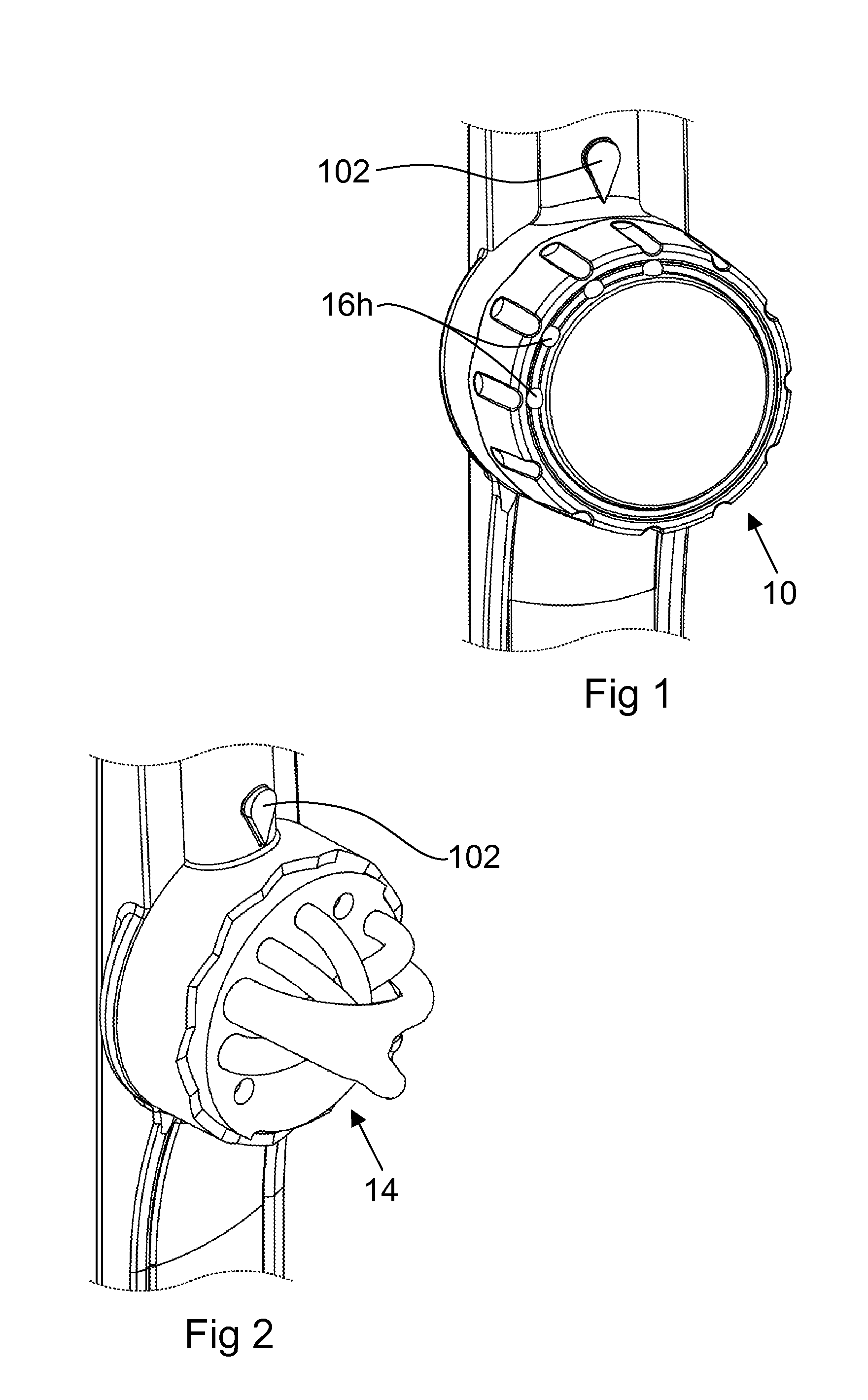
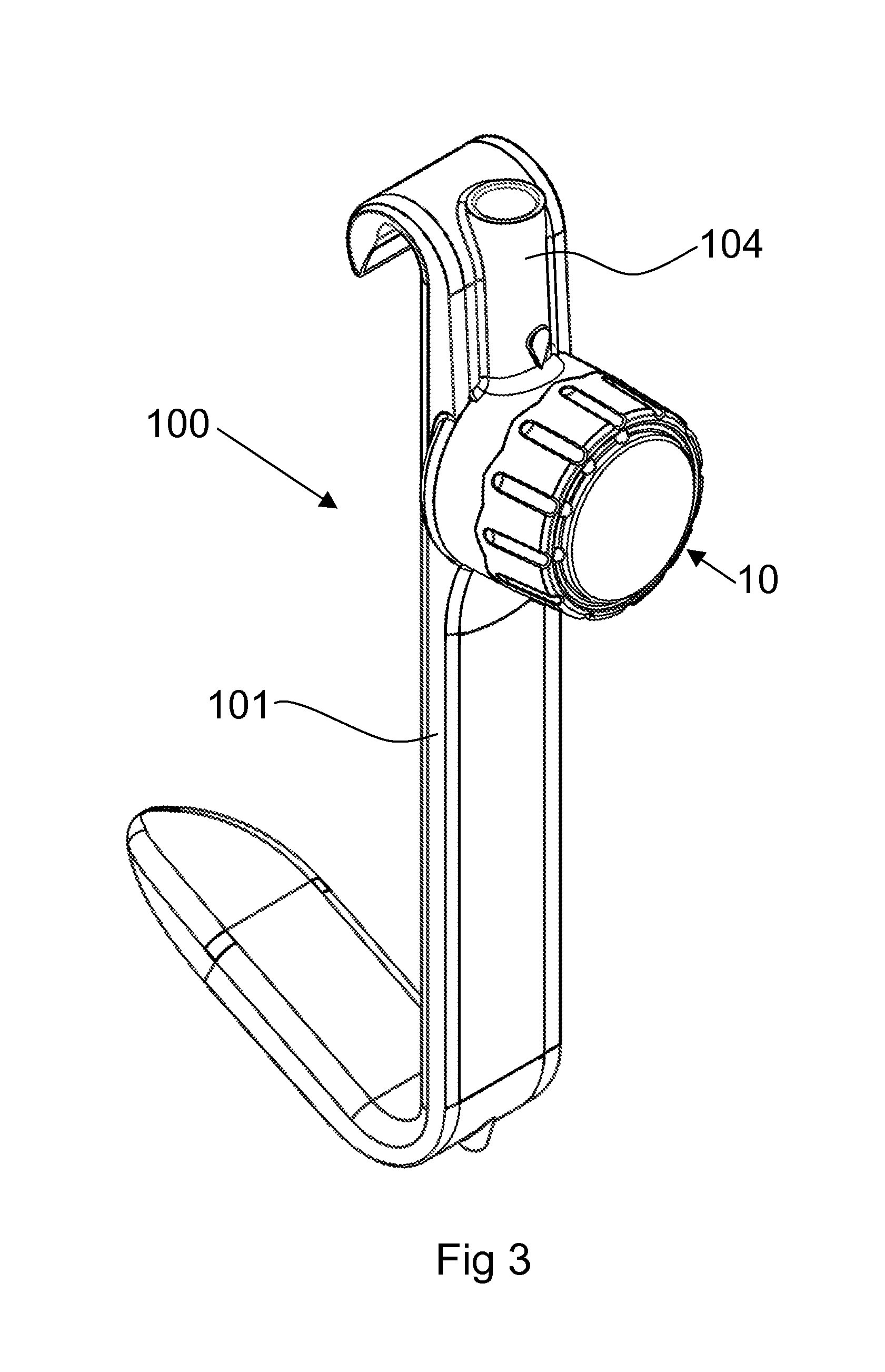
[0042]An optical switch 10 according to a first aspect of the present invention is depicted in FIG. 1. FIG. 3 shows the optical switch as a component part of a surgical retractor 100 according to a third aspect of the present invention.

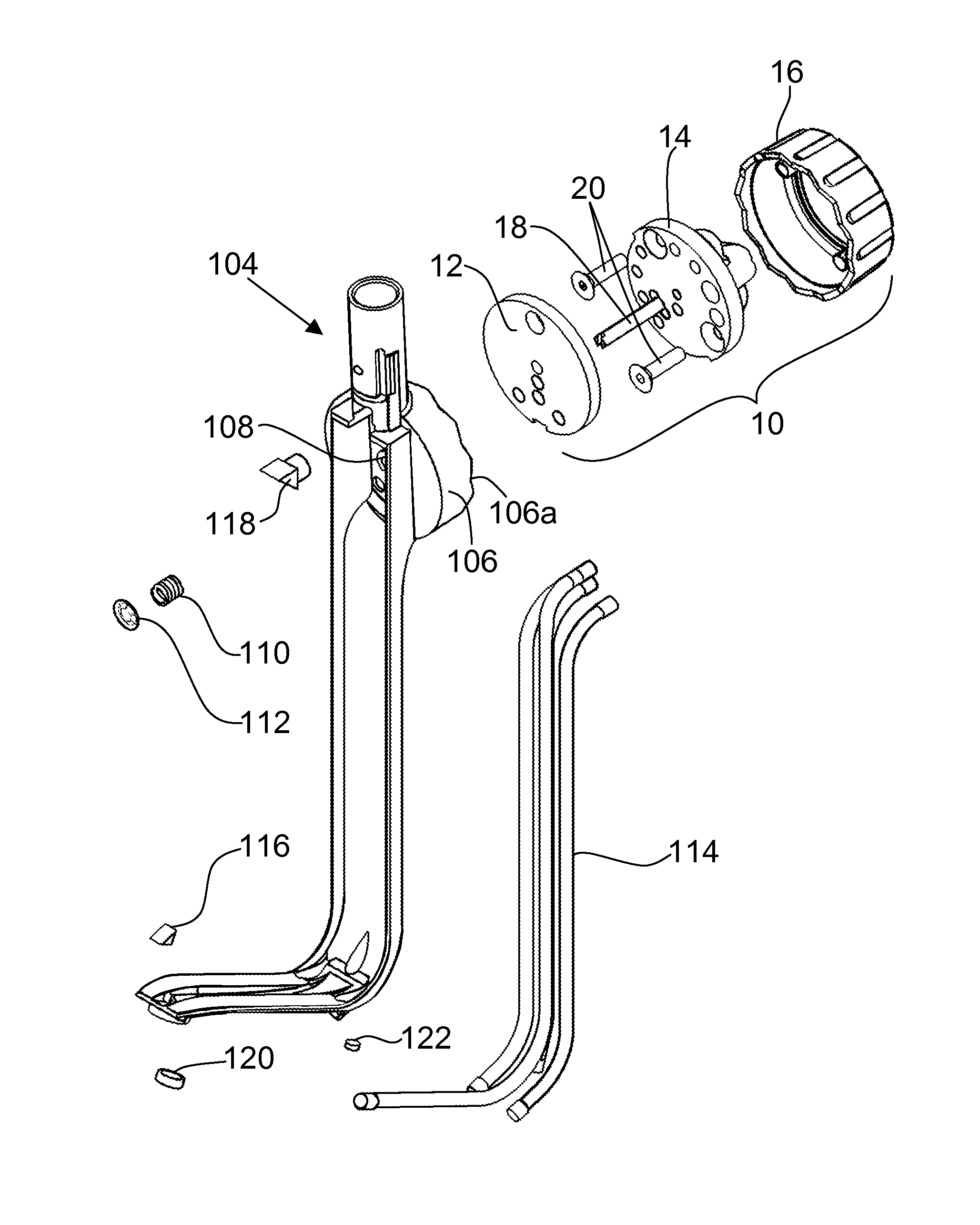
[0043]As can be best seen from FIG. 4, the optical switch 10 comprises a base plate 12, a light pathway plate 14 and a housing 16. These three “major” components are attached together via an axle 18 and fixing bolts 20.

[0044]The base plate 12 is generally circular, or to be more accurate is a cylinder with its facial diameter far exceeding its height.

[0045]The base plate 12 has a number of bores running through it, and these bores define a light input 12a and a plurality of light outputs 12b. Although a single light input 12a is described in the present embodiment, it will be understood that a plurality of light inputs is a possibility, as is a singular light output 12b, or combinations thereof.

[0046]There is a base plate central bore 12c which enable...


PUM


Abstract

An optical switch (10) includes a light input (12a), a plurality of light outputs (12b) and at least one light pathway movable from a first position where a light communication path is formed between a light input (14a) and a first light output (14b) and a second position where a light communication path is formed between the light input and a plurality of light outputs. Multiple light pathways are configured within the switch and selectable by rotation of a switch housing part enabling sequential selection of light communication paths. The switch can be used on a surgical device to control illumination of the surgical field during a procedure.

Description

FIELD OF THE INVENTION[0001]The present invention relates to optical switches, especially those used with fibre optic cables. Moreover, the optical switch finds application in various fields, including surgical retractors with lights, for example that found in the disclosure of International Patent Application No PCT / GB2009 / 000097.BACKGROUND OF THE INVENTION[0002]Fibre optics are used in a variety of industries including aerospace, telecommunications, lasers and medical devices. A common problem involves switching lights on or off and switching light between paths or combinations of paths. A variety of solutions have been developed to fulfill these requirements including (i) beam splitters, (ii) shuttles, (iii) optical shutters and (iv) variation of the shutter concept, the twisted-nematic liquid crystal shutter.[0003]A beam splitter in its most common form is a cube made from two triangular glass prisms, which are glued together at their base using Canada balsam. The thickness of t...

Claims


Application Information

Patent Timeline
Patent Type & Authority Patents(United States)
IPC IPC(8): G02B6/35A61B1/00A61B1/07A61B5/00A61B17/02A61B19/00
CPCG02B6/35A61B1/00126A61B5/00A61B17/02A61B19/5202G02B6/3504G02B6/3574A61B1/07A61B2019/5206A61B2562/0233A61B90/30A61B2090/306
Inventor SUTHERLAND, YINGSUTHERLAND, FRASER WILLIAM HAVERNTARGELL, JOHN
Owner CARDIOPRECISION
Why Eureka
Try Eureka