Electromagnetic relay

a technology of electromagnetic relays and relays, applied in electromagnetic relays, electrical equipment, electromagnetical relay details, etc., can solve the problems of contact overheating and damage, insufficient electromagnetic strength of permanent magnets, and inability to secure adequate insulation in a case, and achieve high arc extinguishing performance

Inactive Publication Date: 2015-04-14
FUJITSU COMPONENENT LTD
View PDF55 Cites 12 Cited by
  • Summary
  • Abstract
  • Description
  • Claims
  • Application Information

AI Technical Summary

Benefits of technology

[0018]According to an aspect of the present invention, a miniaturized electromagnetic relay with high arc extinguishing performance may be provided. Also, an electromagnetic relay may be provided that is capable of securing high insulation between internal parts of the electromagnetic relay.

Problems solved by technology

When arcing occurs, the contacts may be overheated and damaged.
Although the electromagnetic relays disclosed in Patent Documents 1-4 are able to improve the arc extinguishing performance by including permanent magnets, the electromagnetic strength of the permanent magnets may be inadequate in a case where a large amount of current is flown.
Also, in the electromagnetic relays disclosed in Patent Documents 5-7, adequate insulation may not be secured in a case where a high voltage is applied, for example.

Method used


Image

  • Electromagnetic relay
  • Electromagnetic relay
  • Electromagnetic relay

Examples


Embodiment Construction

[0049]In the following, embodiments of the present invention will be described with reference to the accompanying drawings.

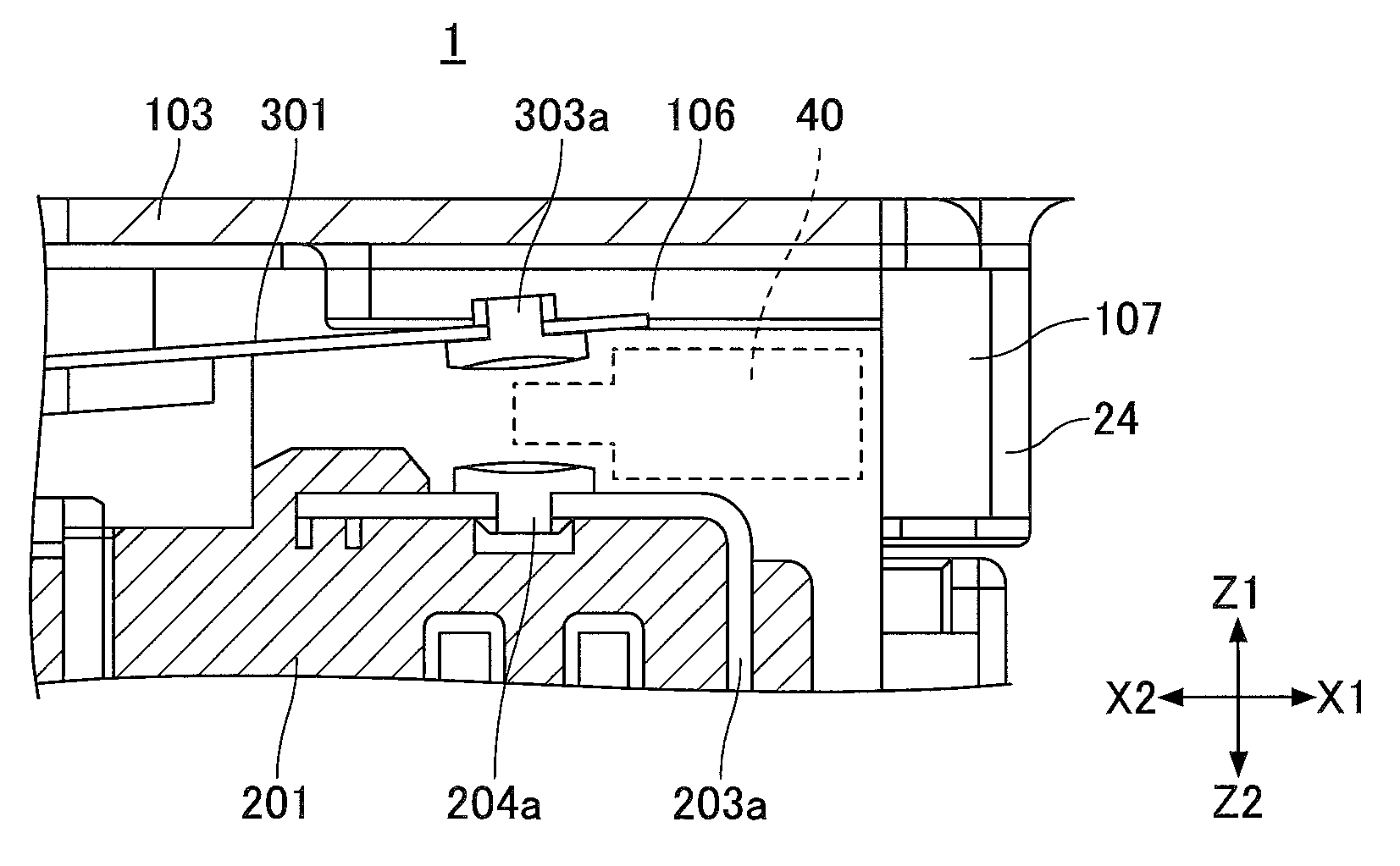
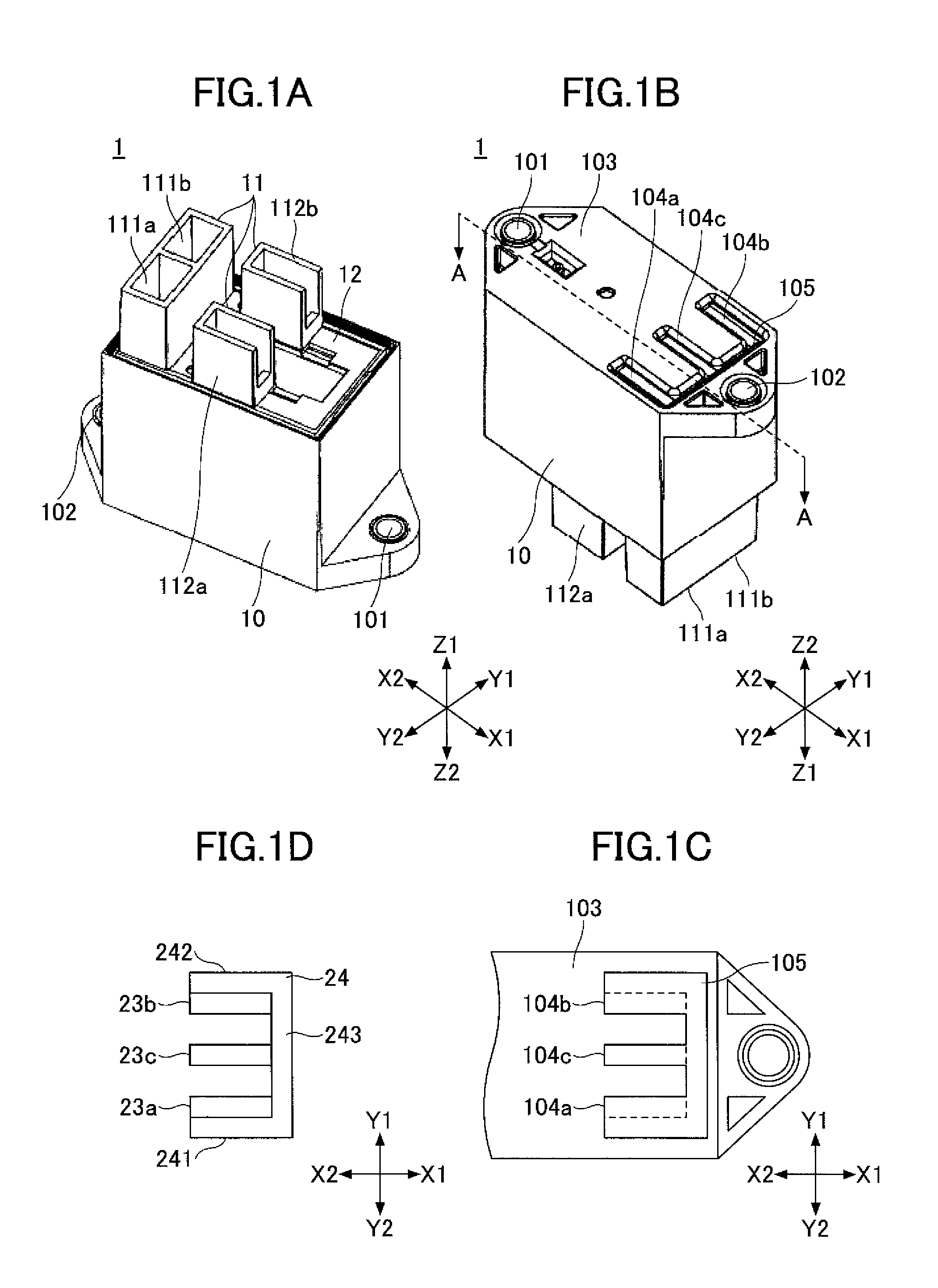
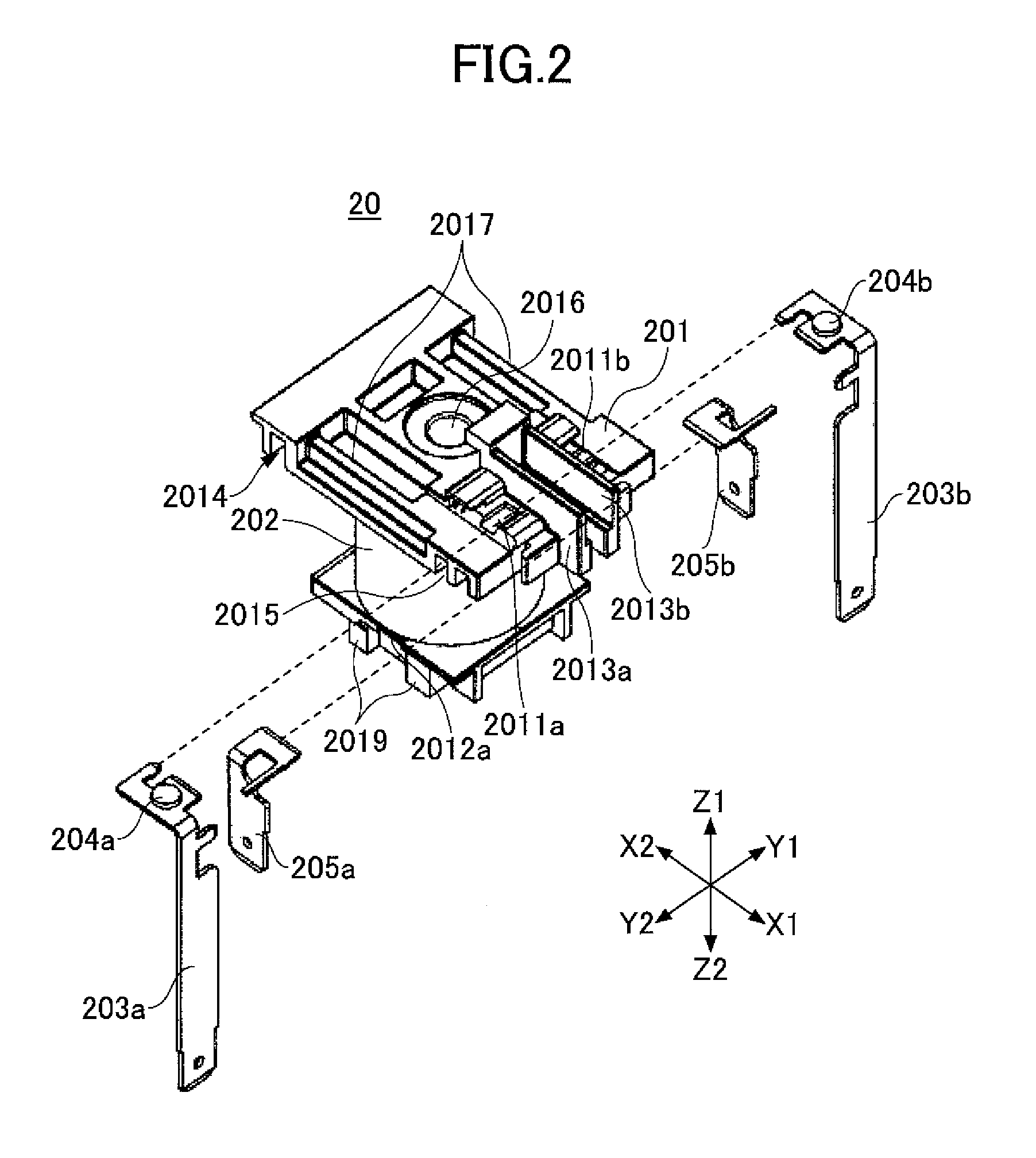
[0050]FIGS. 1A-1D are external views of an electromagnetic relay 1 according to an embodiment of the present invention. FIG. 1A is a perspective view of the electromagnetic relay 1 viewed from a terminal side; FIG. 1B is a perspective view of the electromagnetic relay 1 viewed from a mount surface side; FIG. 1C is an enlarged partial view of the mount surface of the electromagnetic relay 1; and FIG. 1D is a top view of an arrangement of permanent magnets and a yoke to be mounted to the electromagnetic relay 1. FIG. 2 illustrates an exemplary configuration of a coil bobbin assembly 20.

[0051]As illustrated in FIG. 1A, the electromagnetic relay 1 of the present embodiment includes a base cover 10, a base 11, and a cover plate 12. The base cover 10, the base 11, and the cover plate 12 are made of insulating plastic material with flame-resistant properties.

[0052]The ...


PUM


Abstract

An electromagnetic relay includes a first stationary contact; a second stationary contact that is aligned with the first stationary contact in a first direction; a first movable contact that is movable toward / away from the first stationary contact in a second direction perpendicular to the first direction; a second movable contact that is movable toward / away from the second stationary contact in the second direction; and a first permanent magnet and a second permanent magnet that face each other. A first contact part, formed by the first stationary contact and the first movable contact, and a second contract part, formed by the second stationary contact and the second movable contact, are interposed between the first permanent magnet and the second permanent magnet in the first direction. The first permanent magnet and the second permanent magnet extend in a third direction, which is perpendicular to the first direction and the second direction.

Description

BACKGROUND OF THE INVENTION[0001]1. Field of the Invention[0002]The present invention relates to an electromagnetic relay.[0003]2. Description of the Related Art[0004]Electromagnetic relays are devices having a main contact part that breaks or allows an electric current flow between contacts, which may be opened / closed by an electromagnetic force. Because the contacts of the electromagnetic relay are opened / closed by an electromagnetic force, arcing may occur between the contacts when the contacts are opened; namely, when the electric current flow is broken. When arcing occurs, the contacts may be overheated and damaged. In some cases, the contacts may weld together as a result.[0005]In consideration of the highly reliable breakage performance demanded in electromagnetic relays used in a high-voltage DC (direct current) circuit of an electric vehicle or a large DC system, for example, measures are desired for effectively extinguishing arcing that occurs between contacts to improve b...

Claims


Application Information

Patent Timeline
Patent Type & Authority Patents(United States)
IPC IPC(8): H01H51/22H01H9/44H01H50/02H01H50/28H01H50/42
CPCH01H9/443H01H50/42H01H2050/028H01H50/28H01H2050/446
Inventor HIRAIWA, NOBUYOSHISAITO, YASUSHIKAKOIYAMA, YUKIWU, YANFENG
Owner FUJITSU COMPONENENT LTD
Why Eureka
Try Eureka