Rolling bearing cage, rolling bearing and electric steering system of a motor vehicle

a technology of rolling bearings and cages, which is applied in the field of rolling bearings, can solve the problems of damage or even destruction of cages, damage to cages, and even destruction, and achieve the effects of small space requirements, low deformation, and uniform distribution of stresses

Active Publication Date: 2015-04-21
AB SKF
View PDF11 Cites 7 Cited by
  • Summary
  • Abstract
  • Description
  • Claims
  • Application Information

AI Technical Summary

Benefits of technology

[0008]More particularly, the present invention aims to provide a cage for a rolling bearing which has low deformability, a small space requirement and evenly distributes the stresses applied to the cage.
[0009]The present invention also aims to provide a cage permitting significant clearance of the balls in the sockets of the cage, whilst providing low friction between the cage and the rolling elements.
[0012]Thus, due to the presence of clearance between the sockets of the cage and the balls, the interaction between the cage and the balls is reduced. Moreover, the balls are mobile relative to one another, thus reducing the risk of unforeseen deformation in the case of opposing movements of two adjacent balls, for example during a steering movement of the wheels when parking the motor vehicle.

Problems solved by technology

However, in applications at low rotational speed or where the rotational direction changes abruptly, this type of cage causes various problems.
More specifically, when the balls are under load, the cage is severely deformed and comes into contact with the inner race, which causes the damage thereof or even the destruction thereof.
Moreover, when changing the direction of the load applied to the rolling bearing, such as for example when steering the wheels of a vehicle provided with an electric steering system, as described above, when the driver performs manoeuvres to the left and to the right in order to park the vehicle, the cage is also severely deformed, or even destroyed.

Method used


Image

  • Rolling bearing cage, rolling bearing and electric steering system of a motor vehicle
  • Rolling bearing cage, rolling bearing and electric steering system of a motor vehicle
  • Rolling bearing cage, rolling bearing and electric steering system of a motor vehicle

Examples


Embodiment Construction

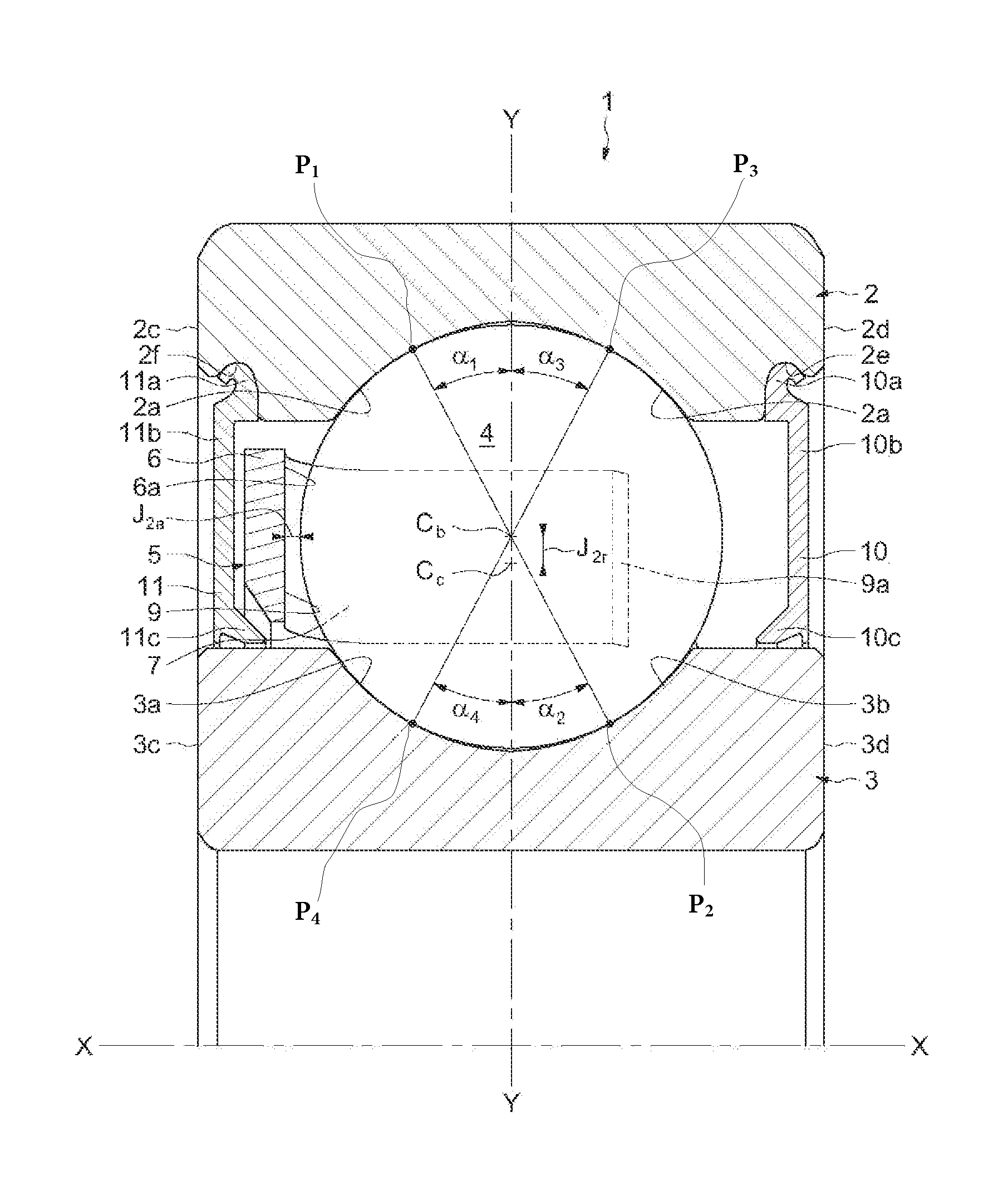
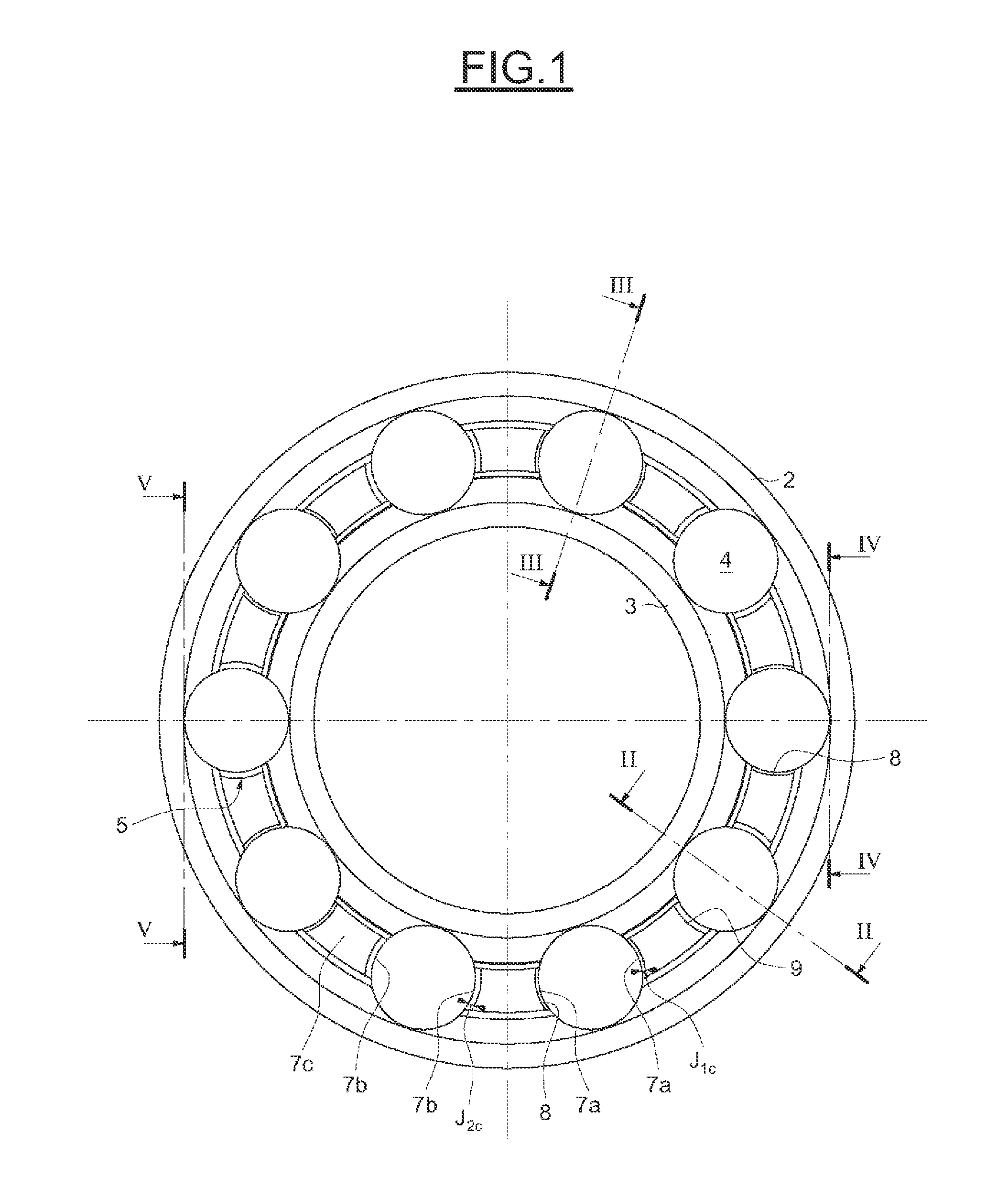
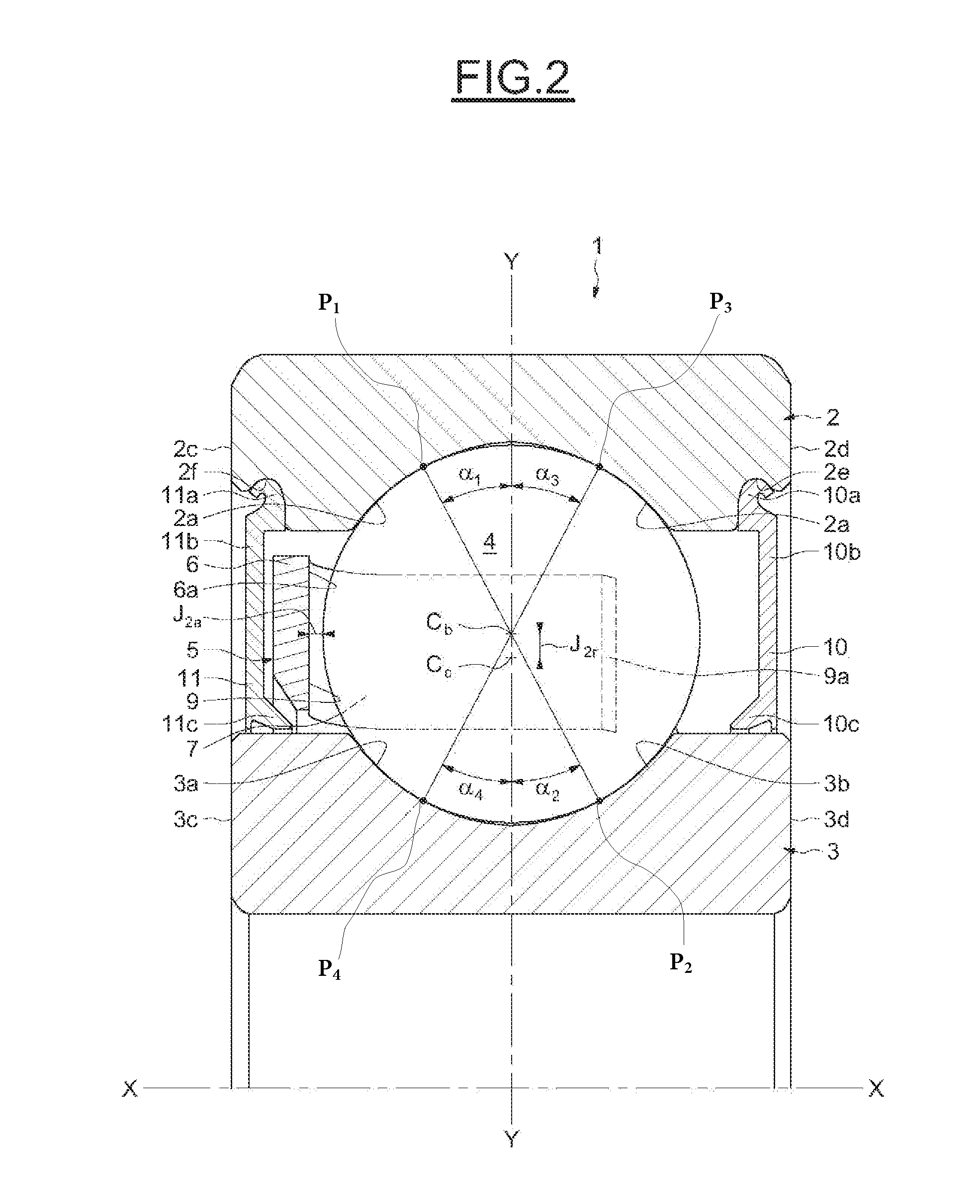
[0026]The rolling bearing, having the axial axis X-X, referenced 1 in its entirety in FIGS. 1 to 4, is designed to be mounted in a steering column of a motor vehicle.

[0027]As illustrated in FIGS. 1 and 2, the rolling bearing 1 comprises an outer race 2, an inner race 3, a set of rolling elements 4, such as balls, and a cage 5 for maintaining the uniform circumferential spacing of the balls 4.

[0028]The inner race 3 is in the form of a ring of generally rectangular section having a small radial thickness and provided on its external surface with two toroidal bearing tracks 3a, 3b. The outer race 2, in a similar manner to the inner race 3, comprises two toroidal bearing tracks 2a, 2b on its internal bore. The inner and outer races 3, 2 have front radial surfaces 3b, 3c, 2b, 2c which are substantially aligned and may each be produced in one piece by machining from one piece of steel.

[0029]Each ball 4 is in contact with the four bearing tracks 2a, 2b, 3a, 3b formed on the inner 3 and out...


PUM


Abstract

Rolling bearing cage (5) for an electric steering system of a motor vehicle, designed to ensure the circumferential spacing of the balls (4), comprising a plurality of first sockets (8) provided with means (8a) for axially retaining the cage (5) on a ball (4) and a plurality of second sockets (9) without means for axially retaining the cage (5) on a ball (4). Each of the first sockets (8), with a ball (4) housed in the first corresponding socket (8), has a first axial clearance, a first radial clearance and a first circumferential clearance (J1c) and each of the second sockets (9), with a ball (4) housed in the second corresponding socket (9), has a second axial clearance, a second radial clearance and a second circumferential clearance (J2c).

Description

CROSS-REFERENCE TO RELATED APPLICATIONS[0001]This application claims priority to French patent application no. 1000156691 filed on Jul. 12, 2012, the contents of which are fully incorporated herein by reference.FIELD OF THE INVENTION[0002]The present invention relates to the field of rolling bearings, in particular ball bearings, used in electric steering systems of motor vehicles. More particularly, the invention relates to cages for retaining the balls, ensuring the circumferential spacing between the balls for such rolling bearings.BACKGROUND OF THE INVENTION[0003]An electric steering system of a motor vehicle generally comprises an electromechanical actuator located on the steering column or on the lower assembly which comprises mechanical members designed to provide the angular positioning of the drive wheels of the vehicle. The electromechanical actuator comprises a rotating electric motor, the shaft thereof being supported by at least one ball bearing device with four points ...

Claims


Application Information

Patent Timeline
Patent Type & Authority Patents(United States)
IPC IPC(8): F16C33/41F16C33/58F16C19/16F16C33/38
CPCF16C33/3887F16C19/166F16C33/416F16C33/418F16C2326/24F16C2240/46F16C2240/40
Inventor ADANE, THIERRYPERROTIN, THOMASVARNOUX, LAURENT
Owner AB SKF
Why Eureka
Try Eureka