System and method for implanting a catheter

a catheter and system technology, applied in the field of system and method for catheter implanting, can solve the problems of catheter buckle, complex operation of catheter implanting and removing intraurethral devices, etc., and achieve the effect of facilitating the placement and placement of the catheter

Active Publication Date: 2015-04-21
INGENION
View PDF34 Cites 11 Cited by
  • Summary
  • Abstract
  • Description
  • Claims
  • Application Information

AI Technical Summary

Benefits of technology

[0007]Accordingly, the present invention relates to an improved system and method for implanting a catheter using an insertion tool that may allow push, pull, and torque to be transmitted from the tool internally through a catheter lumen or channel, and push, pull, and torque to be transmitted through a catheter wall from a distal portion of the catheter to a proximal portion to facilitate location and placement of the catheter in a tubular cavity or hollow organ, thereby enabling the catheter to be implanted.
[0011]Another embodiment ensures the extendible element remains in the socket of the catheter until intentionally removed by providing a constant proximally directed force to the extendible element. This can be achieved by placing a biasing device, such as, for example, an extension spring, in the mechanism that urges the extendible element proximally when the tool is coupled to the catheter. The biasing device places the catheter in a tensionally stressed condition. Any elongation of the catheter will be compensated for by the biasing device, thus maintaining placement of the extendible element in the socket.
[0013]Another embodiment of the present invention is the system in which the element is in a stressed state, and the catheter is in a stressed state, when the mechanism extends the element. The element is constructed of a material and cross section suitable to withstand encountered axial tensile and compressive forces and resulting stresses without distorting or buckling.
[0030]Yet another embodiment of the present invention is the system that also includes a first opening in the valve, a first opening in the tool tip, that aligns with the first opening in the valve. There may also be a second opening in the tool tip aligns with the first opening in the valve, and an extendible element that passes from the first opening in the tool tip through the first opening in the valve and through the second opening in the tool tip, thereby locking the tool tip and the valve together.

Problems solved by technology

Unfortunately, implanting and removing intraurethral devices are complex operations and do not provide immediate confirmation of proper placement of the devices in the urethra.
Further, the tool when pushing the catheter may cause the catheter to buckle as a result of the flexible nature of the catheter.

Method used


Image

  • System and method for implanting a catheter
  • System and method for implanting a catheter
  • System and method for implanting a catheter

Examples


Embodiment Construction

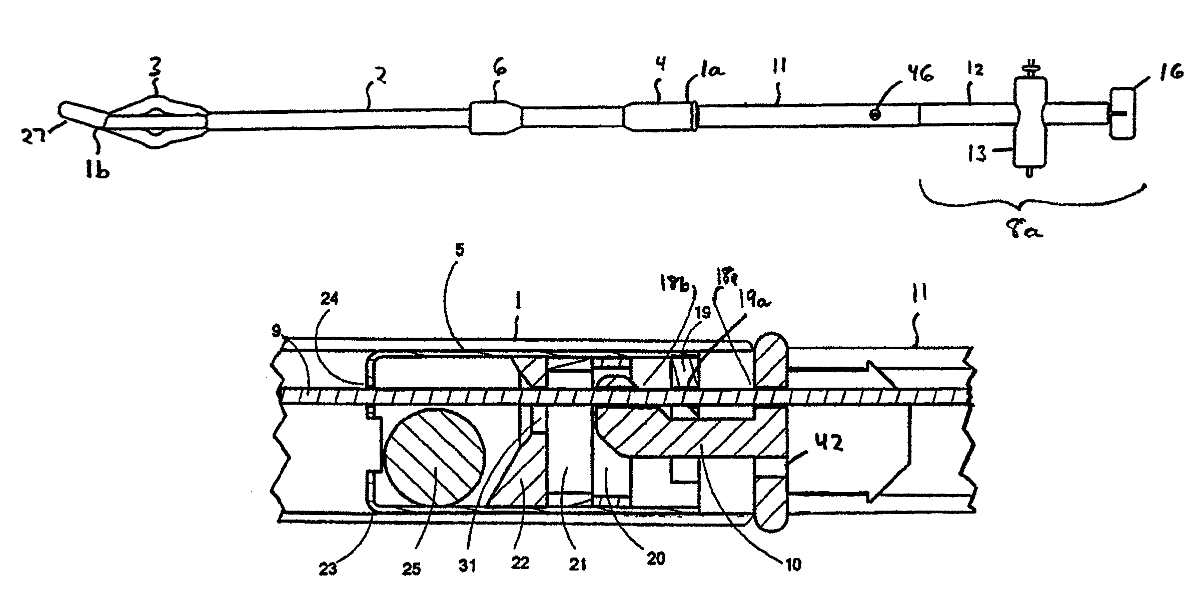
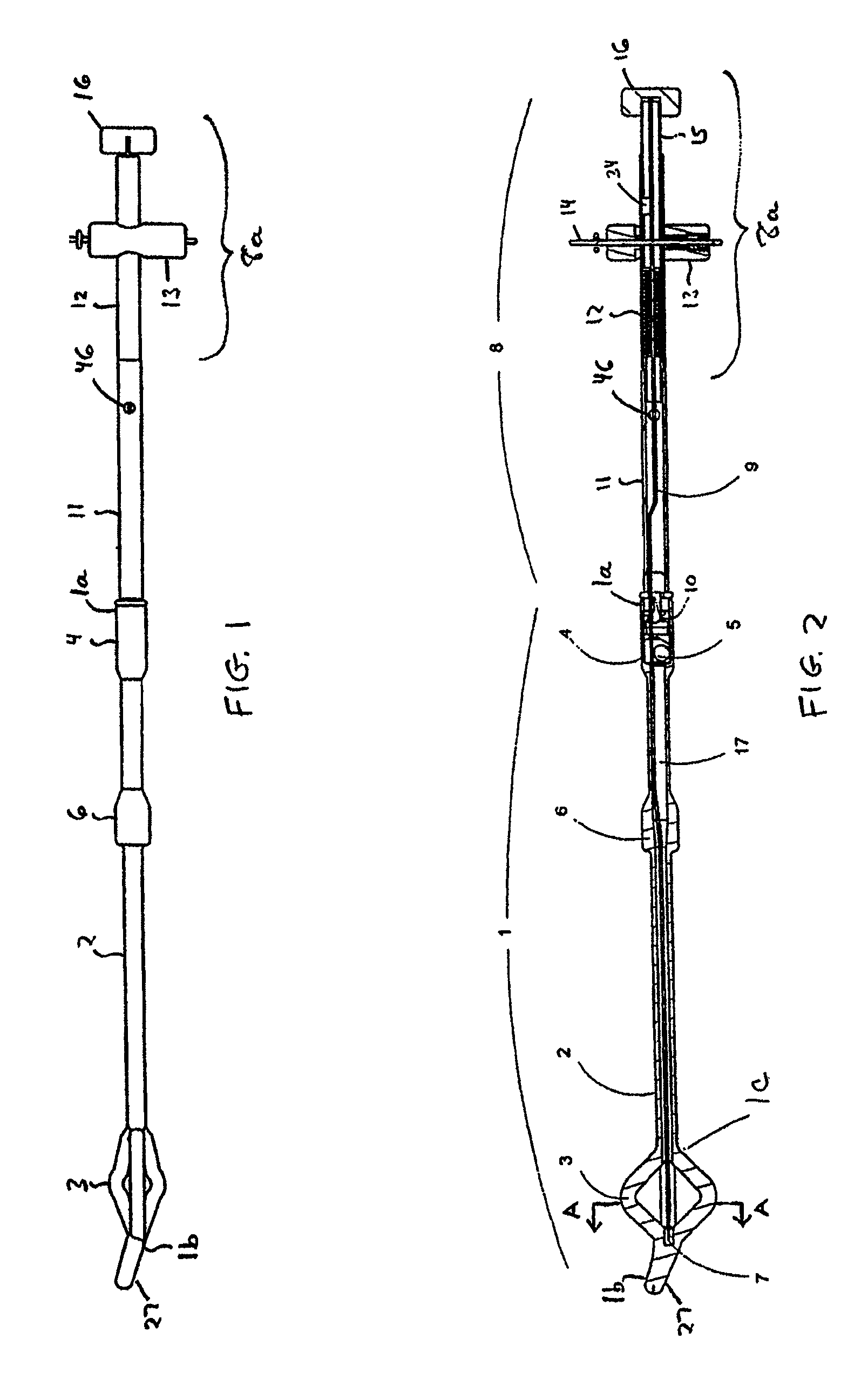
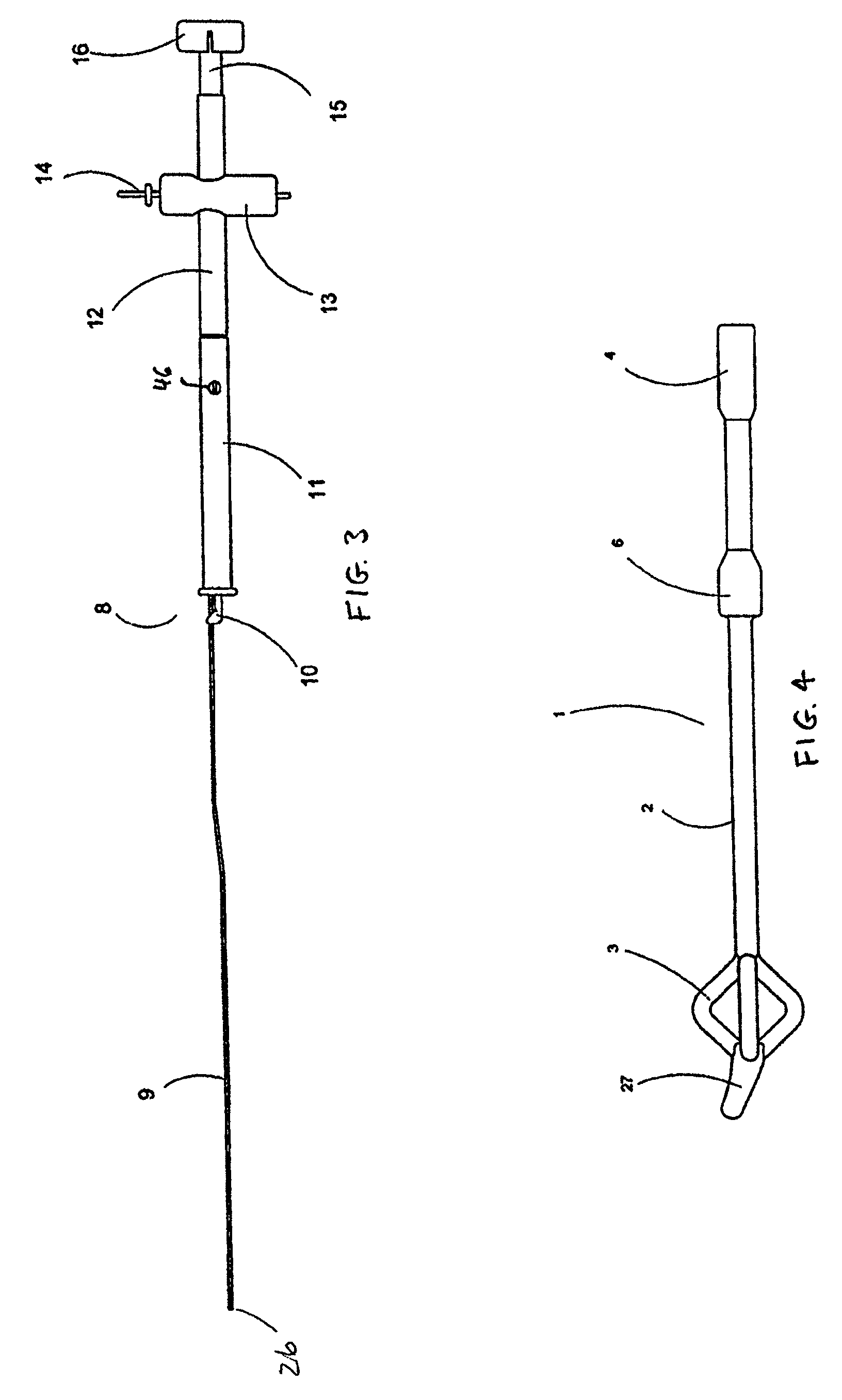
[0055]As used herein, the term “lumen” will be understood to be an inner open space of a tubular cavity or organ and shall be used interchangeably with “channel” throughout the specification. As used herein, the term “valve” will be understood to include magnetically operated valves, other remotely operated valves or manually operated valves suitable for placement within a catheter. As used herein, the anchoring device referred to by the term “malecot” should be understood to include pigtail, balloons, spines, umbrellas, or other configurations of known devices for anchoring catheters placed in hollow organs. For illustrative purposes only, the catheter is described in the specification in terms of a urethral catheter with the understanding that this is one of many potential applications for the instant invention. One skilled in the art will recognize that the catheter disclosed may be used in other applications in which a catheter would be beneficial.

[0056]Generally, the present in...


PUM


Abstract

A system for implanting a catheter in a urethra. The system includes a catheter having a valve disposed at a distal portion of the catheter. The valve may be operable in response to an external magnetic field. The system also includes a tool having a tip member extending into an opening at the distal portion of the catheter to couple the tool to the catheter. the system also includes an element extending from the tool. The catheter has an internal path that provides a conduit for the element to be extended through the valve to engage a proximal portion of the catheter. The tool is adapted use the element to stress the catheter and stiffen the catheter along the length of the catheter. Stiffening the catheter facilitates implantation of the catheter in the urethra by enabling pull forces, push forces, and torque forces to be transmitted from the tool through the catheter to the proximal portion of the catheter without undue stress on the urethra. The element is extendible and retractable to position the catheter between stressed and relaxed states while maintaining engagement to the catheter proximal portion. The tool, element and tip member are removable from the catheter after implantation of the catheter in the urethra.

Description

BACKGROUND[0001]1. Field of the Invention[0002]The present invention relates generally to a system and method for implanting a catheter, such as a catheter having a magnetic valve (a valved catheter), in a tubular cavity or hollow organ. In particular, the present invention relates to a system and method that utilizes an insertion tool suitable for implanting a catheter, for example, in the urethra.[0003]2. Background of the Invention[0004]There are conventional devices for inserting and removing intraurethral sphincter prostheses and / or catheters for treatment of urinary retention deficiencies using devices for detecting, gripping and positioning valves and stents within the urethra. There are also conventional devices that use multi-lumen devices for inflating and deflating stent and / or catheter fixating balloons. There are separate tools for insertion and extraction, and tethers for retrieval of valves and stents.[0005]Unfortunately, implanting and removing intraurethral devices ...

Claims


Application Information

Patent Timeline
Patent Type & Authority Patents(United States)
IPC IPC(8): A61F2/00A61M25/01
CPCA61M25/01A61F2/0009A61F2/0036A61M25/0113A61M25/0136A61M25/0147A61M2210/1089
Inventor DAVIS, PHILLIP JWINEGAR, THOMAS WHOMAN, HARVEY DLEOPOLD, ANDREW R
Owner INGENION
Why Eureka
Try Eureka