Controller and control method for a motorised vehicle

a motorised vehicle and control method technology, applied in the direction of wheelchairs/patient conveyances, speed regulation of multiple dynamo-electric motors, underwater vessels, etc., can solve the problems such as inability to fully solve the described control problems such as turn instability and camber veering, and achieve stable driving experience.

Inactive Publication Date: 2015-04-28
PENNY & GILES CONTROLS
View PDF34 Cites 16 Cited by
  • Summary
  • Abstract
  • Description
  • Claims
  • Application Information

AI Technical Summary

Benefits of technology

[0017]There are a number of ways in which the motor control circuitry could determine an appropriate slowing correction, but in one embodiment said control signals determine a demanded turn radius of the motorised vehicle and said motor control circuitry is configured to apply said slowing correction to preserve said demanded turn radius. It will be appreciated that the control signals from the user input device of the motorised vehicle will determine a demanded turn radius which the user wishes the motorised vehicle to take. Of course this demanded turn radius can be extremely large—when the user wishes to travel in a straight line. By determining the slowing correction so as to preserve the demanded turn radius when a loading imbalance between the left and right motor occurs, the controlling characteristics of the motorised vehicle are improved, since the vehicle responds to the user commands in a manner which more accurately reflects the user's wishes.
[0032]In some embodiments, said motor control circuitry is configured to reduce said slowing correction when an actual speed of said motorised vehicle is less than a predetermined speed. It has been found that the techniques of the technology disclosed are particularly applicable at higher speeds of the motorised vehicle and that a more stable driving experience results when the applied slowing correction is reduced at lower overall speeds of the motorised vehicle.

Problems solved by technology

However, the inventor of the technology disclosed realised that the above described control problems (such as turn instability and camber veer) cannot be fully solved by this known approach, and has found that a significant improvement in the controllability of such motorised vehicles results from providing motor control circuitry configured to monitor both motors and to apply a slowing correction to the less loaded motor, when a loading imbalance is detected.

Method used


Image

  • Controller and control method for a motorised vehicle
  • Controller and control method for a motorised vehicle
  • Controller and control method for a motorised vehicle

Examples


Embodiment Construction

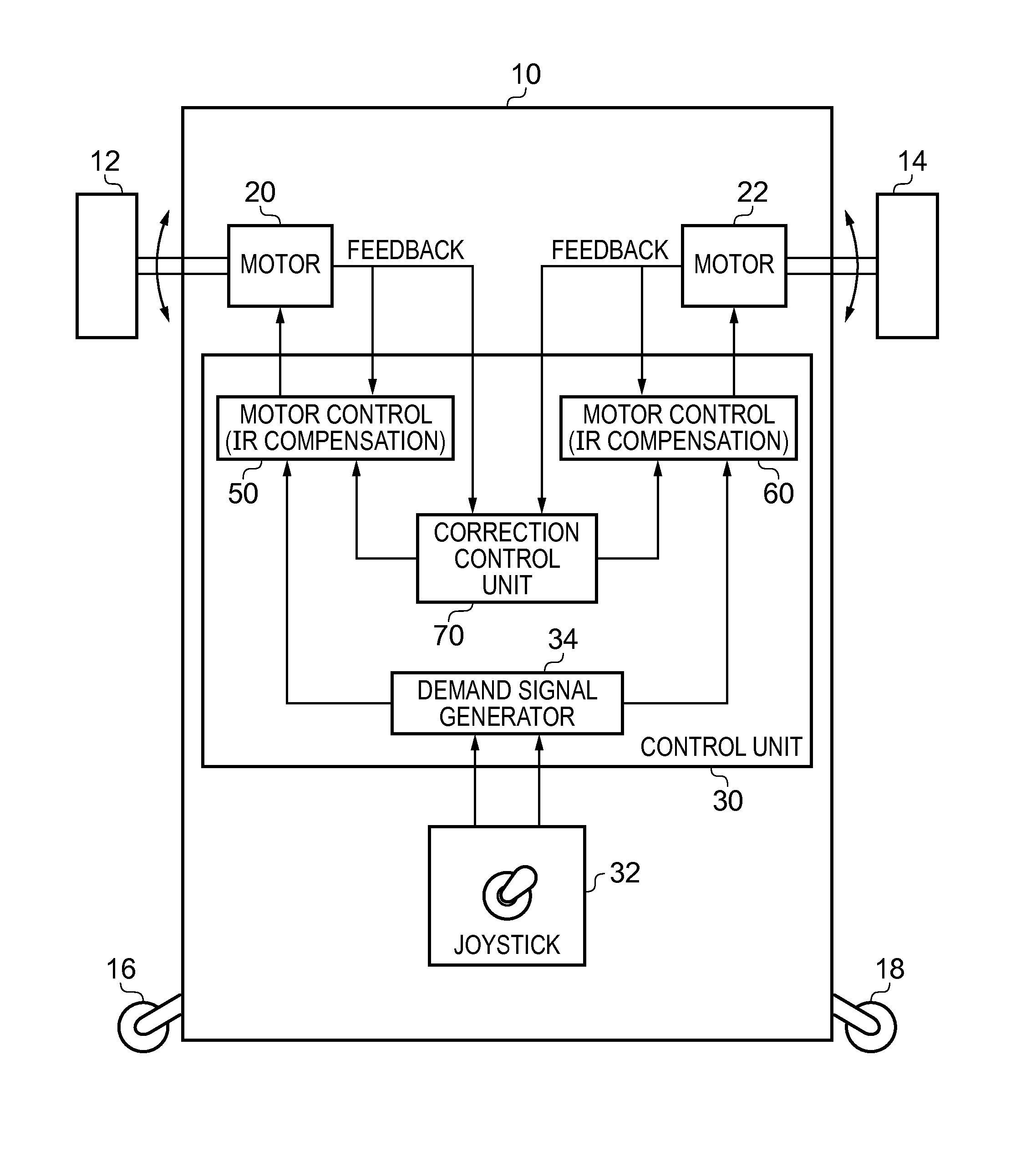
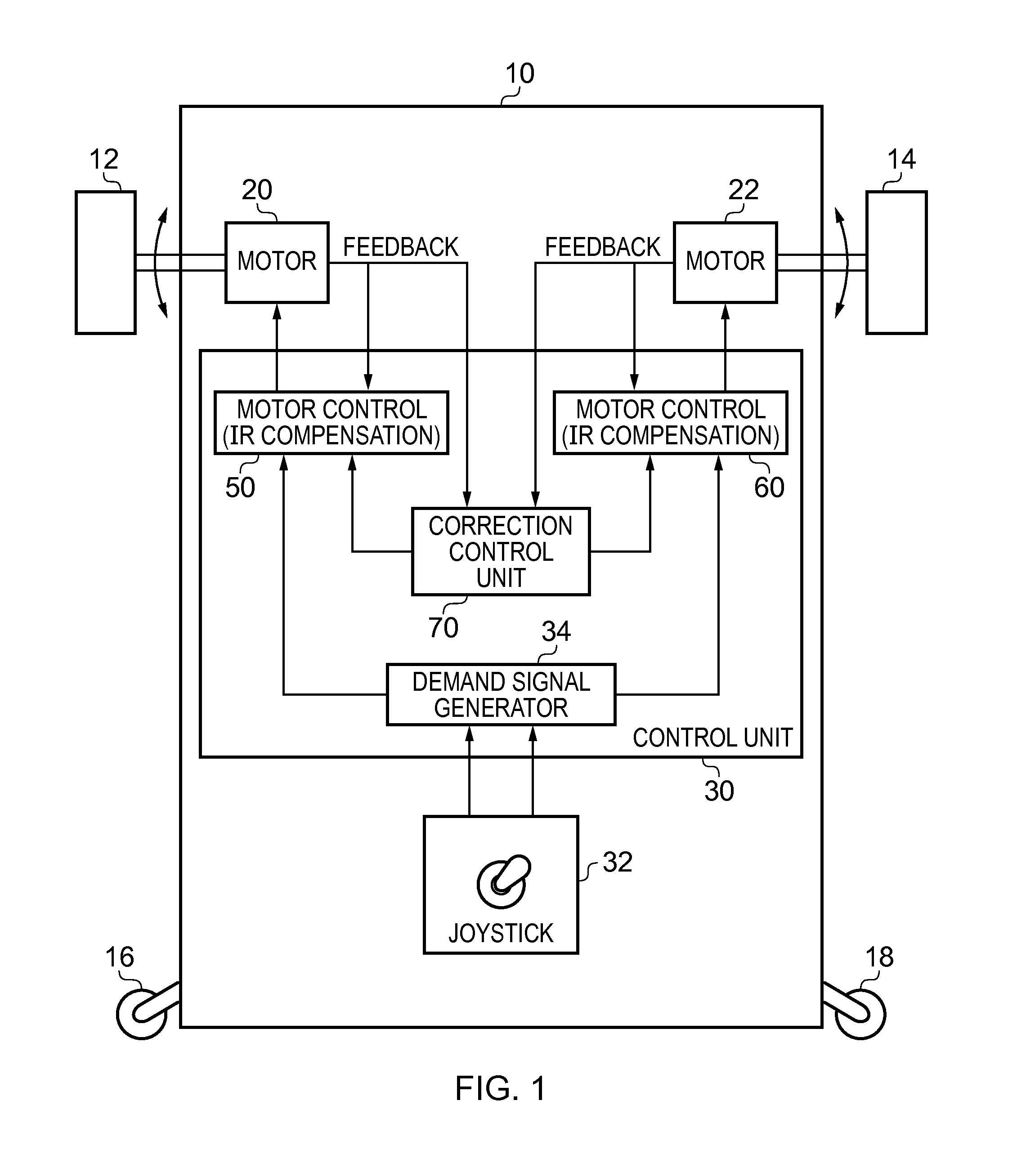
[0050]FIG. 1 is a block diagram of a motorised vehicle in accordance with one embodiment of the present invention. For the purposes of the following discussion, the example where the motorised vehicle is an electric wheelchair will be used. In the example of FIG. 1, the electric wheelchair has a chassis 10 to which two motor driven wheels are connected, namely a left wheel 12 and a right wheel 14. Further, a pair of castors 16, 18 are also provided on the chassis which rotate to follow the direction of travel of the wheelchair. In the illustrated example, the wheelchair is a front wheel drive wheelchair, so that the castors 16, 18 typically follow the direction in which the driven wheels 12, 14 lead (except of course when the wheelchair is in reverse). Each of the two motor driven wheels 12, 14 are driven independently by a motor. In the embodiments illustrated, the left wheel 12 is driven by the motor 20 and the right wheel 14 is driven by the motor 22. To make the vehicle move for...


PUM


Abstract

The technology disclosed relates to a controller and a control method for a motorized vehicle, and in particular to the control of a motorized vehicle having at least a left wheel and a right wheel, the left wheel being driven by a left motor and the right wheel being driven by a right motor. In accordance with such motorized vehicles, linear motion of the vehicle is typically effected by driving the left motor and the right motor in the same direction, while spinning of the vehicle is typically effected by driving the left motor and the right motor in opposite directions. A typical example of such a motorized vehicle is an electric wheelchair.

Description

RELATED APPLICATIONS[0001]This application claims the benefit of United Kingdom Application No. 104985.6, filed Mar. 24, 2010. The priority application is hereby incorporated by reference.[0002]This application is related to U.S. patent application Ser. No. 12 / 780,782 entitled “A Controller and Control Method for a Motorised Vehicle”, filed 14 May 2010. The related application is incorporated by reference.BACKGROUND OF THE INVENTION[0003]1. Field of the Invention[0004]The technology disclosed relates to a controller and a control method for a motorised vehicle, and in particular to the control of a motorised vehicle having at least a left wheel and a right wheel, the left wheel being driven by a left motor and the right wheel being driven by a right motor. In accordance with such motorised vehicles, linear motion of the vehicle is typically effected by driving the left motor and the right motor in the same direction, whilst spinning of the vehicle is typically effected by driving th...

Claims


Application Information

Patent Timeline
Patent Type & Authority Patents(United States)
IPC IPC(8): B62D11/00B62D11/02B60L3/10
CPCB60L3/102Y02T10/7258A61G5/04B60L15/2036B60L2200/34B60L2220/46B60L2240/421B60L2240/427B60L2240/429B60L2250/12B60L2250/24B60L2260/42Y02T10/64Y02T10/72B62D5/04
Inventor TROWELL, MATTHEW JOHNLEWIS, JASON DAVID
Owner PENNY & GILES CONTROLS
Why Eureka
Try Eureka