Image processing apparatus, image processing method and image printing apparatus

a technology of image printing and image processing, which is applied in the field of image printing apparatus, can solve the problems of insufficient low rub fastness of the ink layer, and inability to produce images with a desired rub fastness in some cases, so as to reduce the dynamic surface tension, increase the graininess of the image, and reduce the rub fastness of the resulting image

Active Publication Date: 2015-04-28
CANON KK
View PDF5 Cites 0 Cited by
  • Summary
  • Abstract
  • Description
  • Claims
  • Application Information

AI Technical Summary

Benefits of technology

[0017]Accordingly, the present application provides an image processing apparatus, an image processing method and an image printing apparatus adapted to print an image in a process in which an ink containing a polymer emulsion and a water-soluble organic solvent and having a relatively low dynamic surface tension is used so as to prevent the decrease in the rub fastness of the resulting image and the increase in graininess of the image.

Problems solved by technology

Images printed by this ink jet printing method, unfortunately, can exhibit low rub fastness.
The present inventors however has found that some of the inks containing a polymer emulsion and a water-soluble organic solvent do not produce images having a desired rub fastness in some cases.
In the region where such an unsatisfactory film of the polymer emulsion is formed, the rub fastness of the ink layer is so insufficient as the image is much likely to separate from the printing medium if rubbed.

Method used


Image

  • Image processing apparatus, image processing method and image printing apparatus
  • Image processing apparatus, image processing method and image printing apparatus
  • Image processing apparatus, image processing method and image printing apparatus

Examples


first embodiment

[0039]A first embodiment of the invention will now be described in detail.

FIG. 3 is a perspective view in partial interior of an image printing apparatus 1000 according to the present embodiment.

FIG. 4 is a schematic side view in partial interior of the image printing apparatus 1000 of the present embodiment.

[0040]The image printing apparatus 1000 contains a housing 1 and a platen 2 above the housing 1. The platen 2 has a plurality of suction holes 34 that suck a printing medium 3 to keep the medium from floating. The suction holes 34 communicate with a duct 4. The printing medium 3 is sucked to the platen 2 by the operation of a suction fan 36 disposed under the duct 4.

[0041]A carriage 6 is held for reciprocal movement in directions parallel to the X direction (scanning direction) by a main rail 5 extending along the longitudinal direction of the housing 1. The carriage 6 contains an ink jet printing head 7. The ink jet printing technique applied to the printing head 7 may be selec...

second embodiment

[0155]The first embodiment has described a technique in which inks having relatively low dynamic surface tensions are ejected in all the scanning operations.

[0156]In the second embodiment, an ink having a relatively low dynamic surface tension is not ejected in a specific one of all the scanning operations performed on a unit region. In the following description, only ink ejection opening line 22K for the black ink and ink ejection opening line 22M for the magenta ink will be described below for the sake of simplicity.

[0157]The description of the same operations as in the first embodiment will be omitted.

[0158]In the present embodiment, an image formation in a unit region 80 on a printing medium is completed by 8 print scanning operations. The printing head 7 used in the present embodiment includes ejection opening line 22K having ejection openings through which a black ink is ejected, and ejection opening line 22M having ejection openings through which a magenta ink is ejected. In ...

third embodiment

[0166]In the first and the second embodiment, mask patterns having different dot connectivities are used according to the dynamic surface tension.

[0167]In a third embodiment, mask patterns having different dot connectivities are used according to not only the dynamic surface tension, but also the amount of ink ejected.

[0168]The description of the same operations as in the first or second embodiment will be omitted.

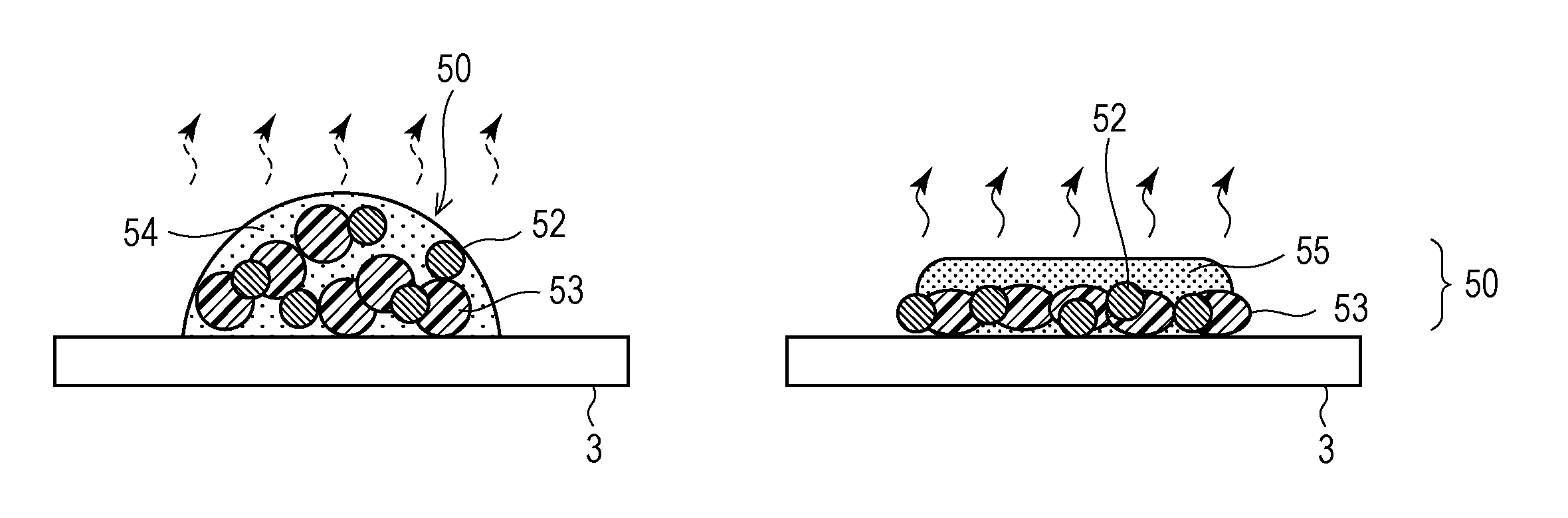
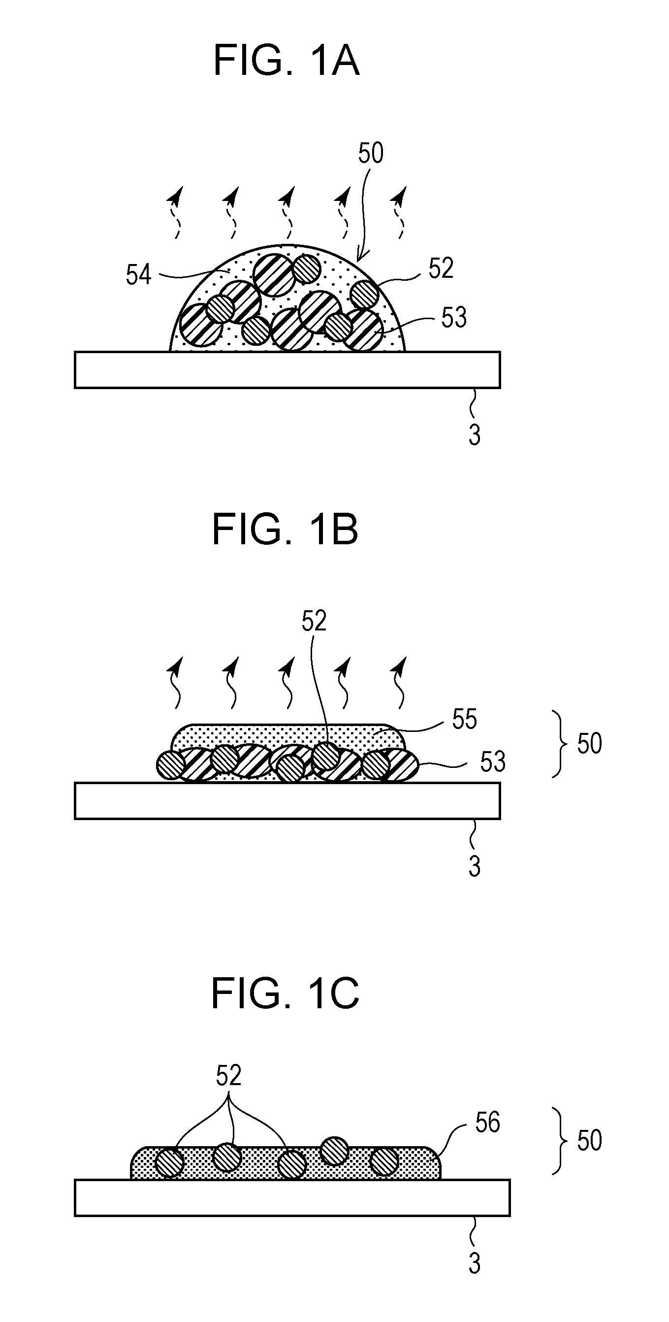
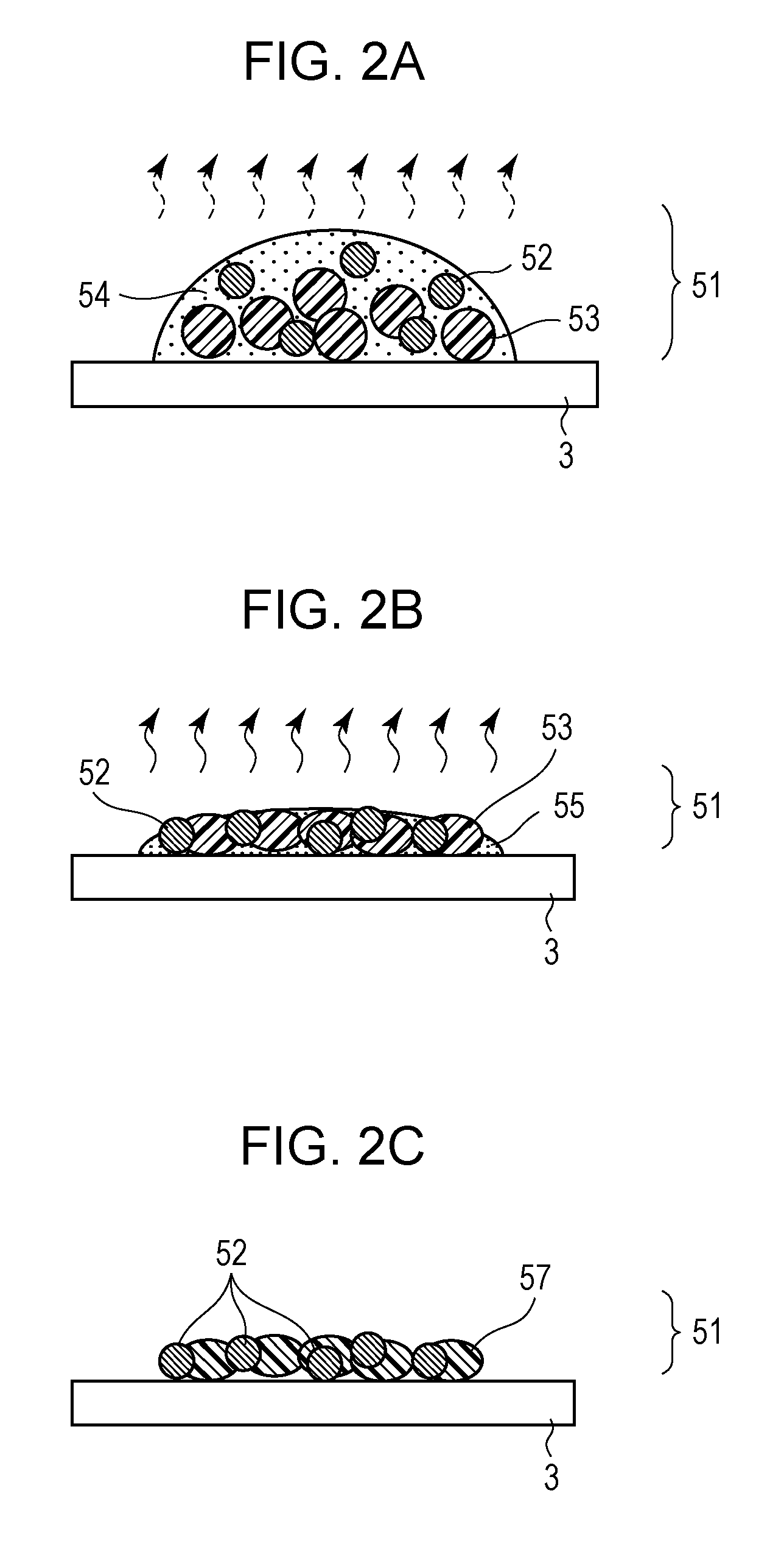
[0169]When an ink is ejected to a less absorbent printing medium, in practice, the ink droplets spread generally over the surface of the printing medium beyond the area of the pixel. Accordingly, when a large amount of ink is ejected, a plurality of ink droplets can join into a larger dot on the printing medium even if mask patters having low dot connectivities are used. Therefore, when a large amount of ink is ejected as in the present embodiment, the polymer emulsion can coalesce into a film sufficiently, and accordingly graininess is unlikely to increase even if an ink ...


PUM


Abstract

When an image is printed with inks each containing a polymer emulsion and a film forming agent, the ejection of the inks is controlled so that the ink having a relatively low dynamic surface tension forms dots having a higher dot connectivity than the dots formed with the ink having a relatively high dynamic surface tension.

Description

BACKGROUND OF THE INVENTION[0001]1. Field of the Invention[0002]The present application relates to an image processing apparatus, an image processing method, and an image printing apparatus.[0003]2. Description of the Related Art[0004]An ink jet printing method has been known which forms an image on a printing medium by repeating a sequence of scanning operation for printing (hereinafter referred to as print scanning operation) and sub-scanning operation for conveying the printing medium. For the print scanning operation, a printing head ejects ink through a plurality of ejection openings arranged therein while scanning the printing medium.[0005]In such an ink jet printing method, in general, a plurality of ink droplets are ejected to different positions apart from each other by each scanning operation, from the viewpoint of reducing the graininess of the printed image. US 2007 / 0097164 discloses a printing method using mask patterns the print permitting pixel patterns of which have ...

Claims


Application Information

Patent Timeline
Patent Type & Authority Patents(United States)
IPC IPC(8): B41J2/205B41J2/045B41J2/21
CPCB41J2/04501B41J2/21G06K15/107B41J2/155
Inventor SHIMMOTO, TATSUOIZUMIZAKI, MASAMINAGASE, YOSHIYUKIOOTA, TAKESHIOGATA, TAKAOKUNIMINE, NOBORU
Owner CANON KK
Why Eureka
Try Eureka