Variable performance vaneaxial fan with high efficiency

a vaneaxial fan, high efficiency technology, applied in the direction of rotors, vessel construction, marine propulsion, etc., can solve the problems of high temperature, turbulence at the rotor tip, and frequent exposure to corrosive chemicals in the airflow of conventional unducted or axial fans, and achieve the effect of variable performance and efficient operation

Active Publication Date: 2015-04-28
CORNERSTONE RES GROUP
View PDF9 Cites 11 Cited by
  • Summary
  • Abstract
  • Description
  • Claims
  • Application Information

AI Technical Summary

Benefits of technology

[0015]The ideal design for a fan with variable performance can replace a family of current vaneaxial fan designs by providing the capability for efficient operation over a range of flow rates and total pressures. This level of variability would not only allow the fan to respond to changing environmental conditions but also be used in systems with different characteristics.

Problems solved by technology

Due to the extreme environments in which they are often used, these fans are frequently subject to corrosive chemicals, high temperatures and abrasive air streams.
Airflow across conventional unducted or axial fans tends to generate turbulence and inefficiencies at the rotor tips.
The increased air turbulence reduces fan efficiency and increases the noise generated by the fan.
They also require high total pressures due to the resistance generated by the airflow through the duct network.
However, the motor size, air flow efficiency, noise generated by the fan, and related factors continue to be problematic in the industry.
By varying the motor RPM of a fan to vary the speed of the rotation of the fan rotor, the flow rate and pressure can be altered within a duct system; however, without altering the geometry of the fan the efficient flow rate and pressure operation points are limited.
In cases where system resistance changes due to dampers or other flow control measures or blockages, variable speed alone might not efficiently achieve the flow rate and total pressure required.
In the worst case scenario, the changing system resistance can result in an operating point that is beyond the stall threshold for the fan, which can result in damage to the fan and system.
Current fan designs cannot achieve high efficiency at a wide range of pressures and flow rates due to their geometric constraints, rotation speed limitations, and limitations in the efficient operating range of the motors and controllers.

Method used


Image

  • Variable performance vaneaxial fan with high efficiency
  • Variable performance vaneaxial fan with high efficiency
  • Variable performance vaneaxial fan with high efficiency

Examples


Embodiment Construction

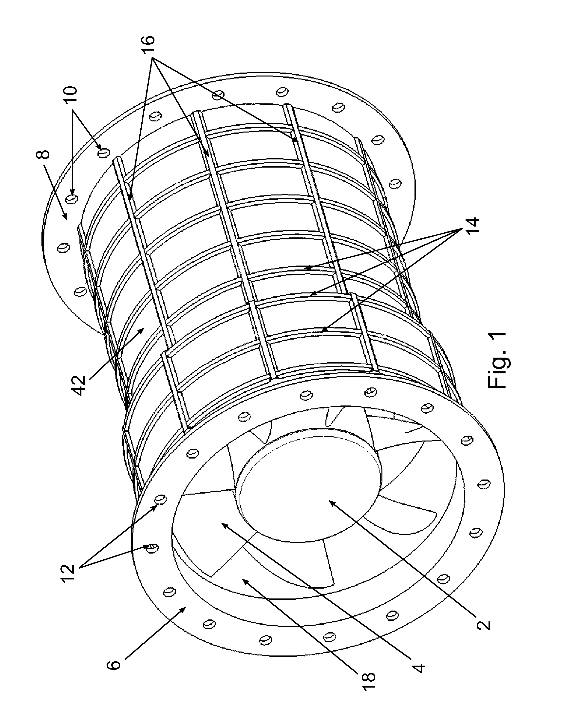
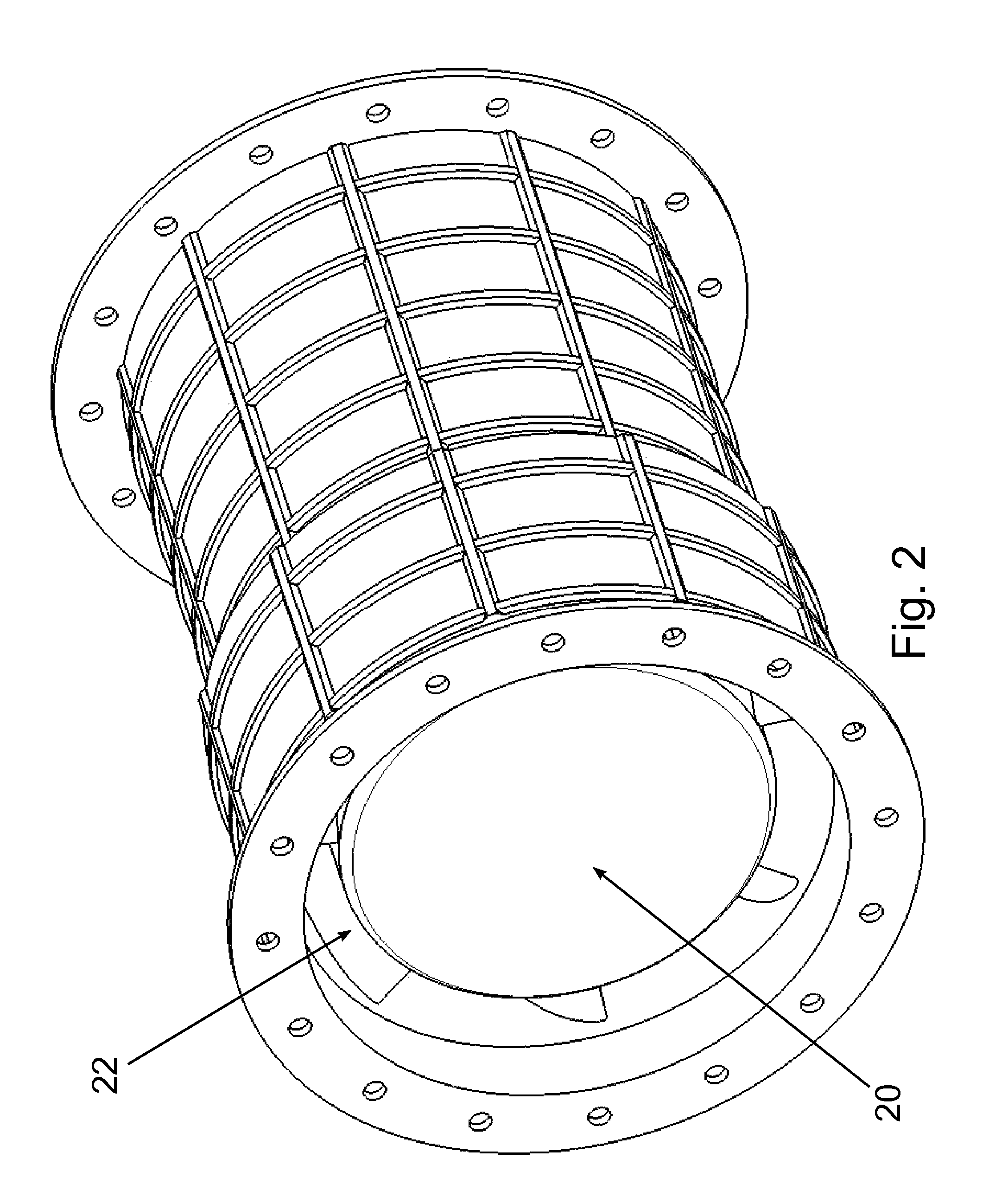
[0027]The design of a high efficiency, variable performance vaneaxial fan requires the utilization of typical fan and single stage compressor design methodologies. To be able to replace multiple fans, the variable vaneaxial fan design must be capable of operation at several different flow rate and total pressures. The disclosed design accomplishes this by varying motor revolutions per minute (RPM) or geometric parameters such as the hub diameter as well as blade geometry including rotor pitch and stator pitch during operation. Additionally the length of the blades, the number of blades, and spacing of the blades can vary for each fan design to meet changing operational requirements.

[0028]An ideal design with variable performance can replace a family of current fan designs by providing the capability for efficient operation over a range of flow rates and total pressures. This level of variability would not only allow the fan to respond to changing environmental conditions but also to...


PUM


Abstract

The design of a high efficiency, variable performance vaneaxial fan, requires the utilization of typical fan and single stage compressor design methodologies. To be able to replace multiple fans, the variable vaneaxial fan design must be capable of operation at several different flow rates and total pressures. These operation points can be met by varying motor revolutions per minute (RPM) or geometric parameters such as the hub diameter, tip diameter, as well as blade geometry including number of blades, pitch, spacing, and length. An ideal design with variable performance can replace a family of current fan designs by providing the capability for efficient operation over a range of flow rates and total pressures. This level of variability would not only allow the fan to respond to changing environmental conditions but also to be fit into systems with different characteristics.

Description

CROSS REFERENCE TO RELATED APPLICATIONS[0001]This application claims priority from U.S. Provisional Application Ser. No. 61 / 232,493 filed Aug. 10, 2009.STATEMENT REGARDING FEDERALLY SPONSORED RESEARCH OR DEVELOPMENT[0002]This invention was made with U.S. Government support under Contract No. N00014-09-M-0091 awarded by the Office of Naval Research to Cornerstone Research Group Inc. The U.S. Government has certain rights in the inventionBACKGROUND OF THE INVENTION[0003]1. Field of the Invention[0004]Vaneaxial fans are axial flow fans which offer high flow rates and total pressures in an in-line configuration. This application discloses a variable vaneaxial fan design which is capable of energy-efficient operation at multiple flow rates and total pressures. The disclosed design accomplishes this by varying motor revolutions per minute (RPM) or geometric parameters such as the hub diameter as well as blade geometry including rotor pitch and stator pitch. In order to optimize each fan d...

Claims


Application Information

Patent Timeline
Patent Type & Authority Patents(United States)
IPC IPC(8): F04D29/46F04D29/52F04D29/64F04D19/00F04D27/00F04D27/02
CPCF04D29/644F04D29/64F04D19/002F04D27/0261F04D27/002F04D27/004Y02B30/70
Inventor PELLEY, BRYAN M.HEMMELGARN, CHRIS D.ALTHAUS, JOSEPH H.FRIES, JENNIFER M.
Owner CORNERSTONE RES GROUP
Why Eureka
Try Eureka