Golf putter and method
- Summary
- Abstract
- Description
- Claims
- Application Information
AI Technical Summary
Benefits of technology
Problems solved by technology
Method used
Image
Examples
Embodiment Construction
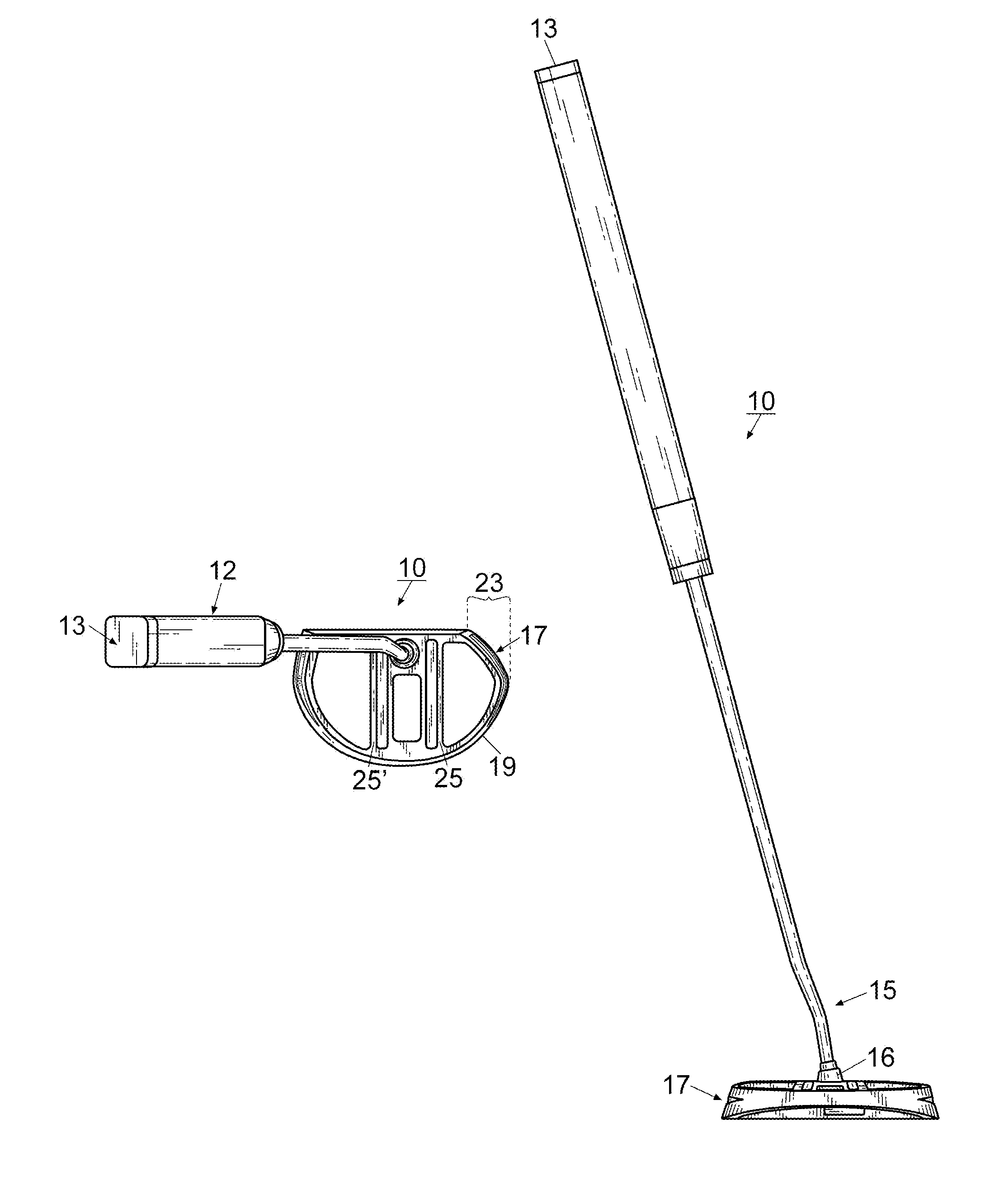
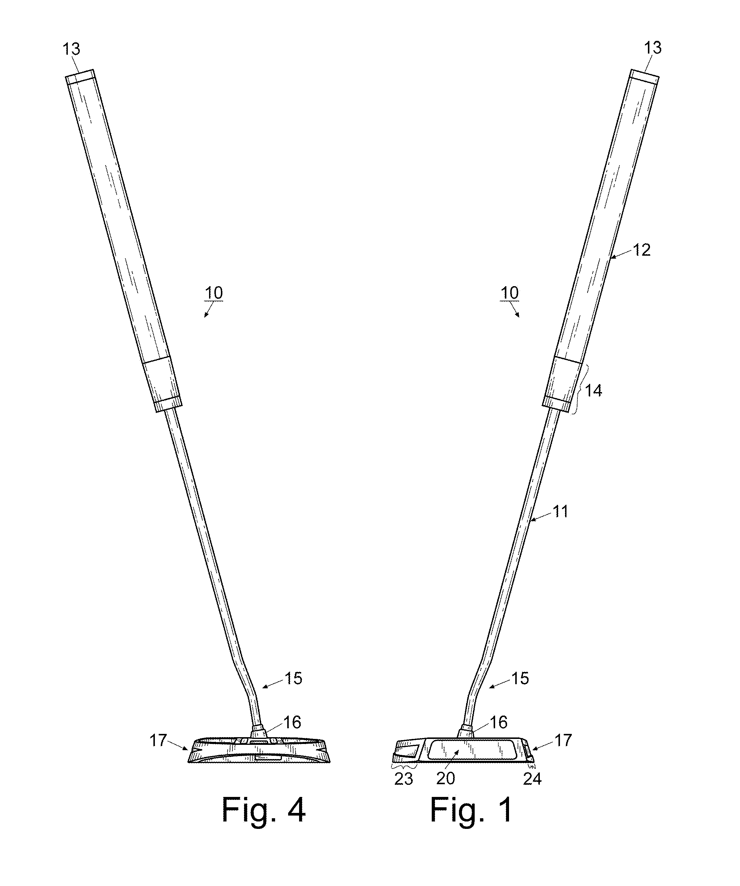
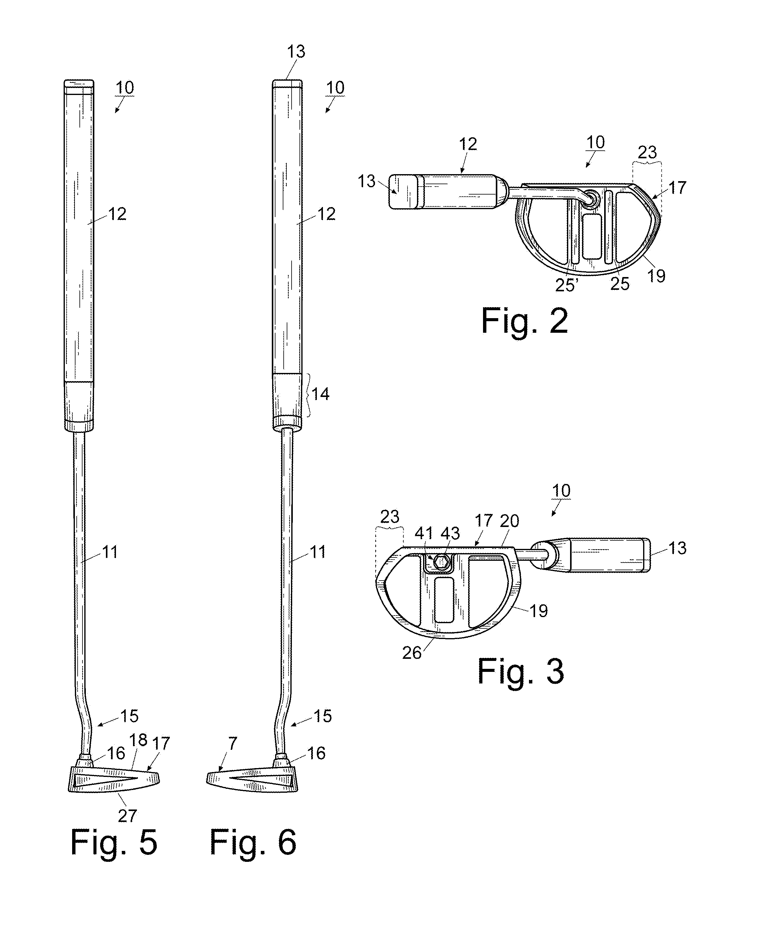
[0031]For a better understanding of the invention and its operation, turning now to the drawings, FIG. 1 shows a front view of preferred putter 10 having shaft 11 and grip 12 which is formed from a standard resilient polymeric foam material. Grip 12 defines a rectangular cross section and includes grip top 13. Grip 12 extends along shaft 11 approximately one half the shaft length and includes a short tapered length 14 at the bottom thereof. Shaft 11 is a conventional shaft preferably formed from metal although other suitable materials such as aluminum, steel, carbon fiber, or other polymeric blends may be utilized. Although preferred golf club 10 is represented in FIGS. 1-9 as a putter, it is understood that club 10 may take on any of a myriad of designs, both of putters and for other clubs.
[0032]As shown in FIGS. 2, 4, 5 and 6, smooth shaft 11 includes an S-shaped bend (seen generally at 15) immediately above hosel 16. Bend 15 is such that when it connects to head 17 it places face...
PUM
 Abstract
Description
Claims
Application Information
 - R&D
- Intellectual Property
- Life Sciences
- Materials
- Tech Scout
- Unparalleled Data Quality
- Higher Quality Content
- 60% Fewer Hallucinations
Browse by: Latest US Patents, China's latest patents, Technical Efficacy Thesaurus, Application Domain, Technology Topic, Popular Technical Reports.
© 2025 PatSnap. All rights reserved.Legal|Privacy policy|Modern Slavery Act Transparency Statement|Sitemap|About US| Contact US: help@patsnap.com


