

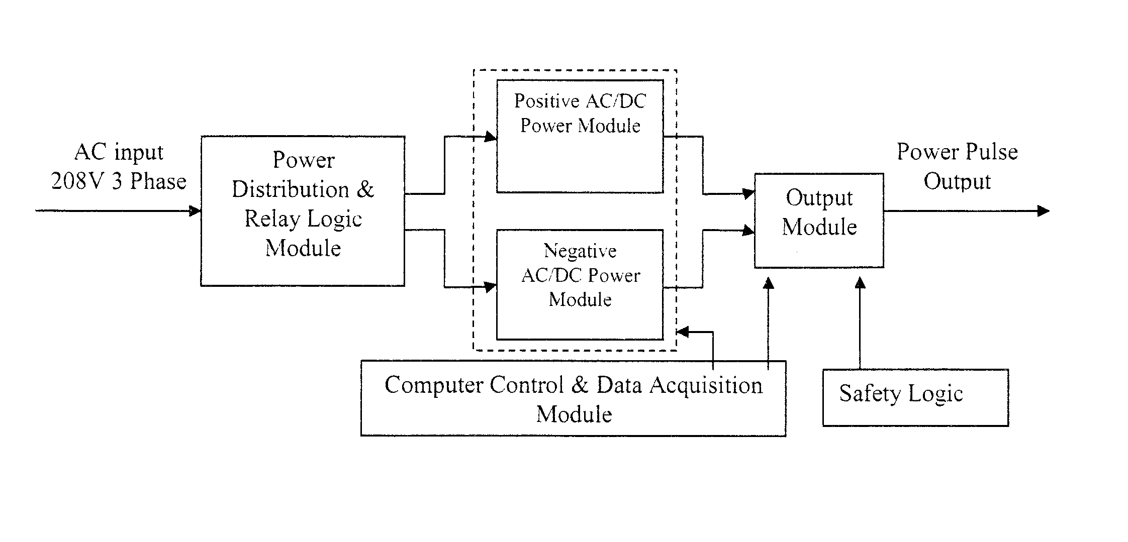
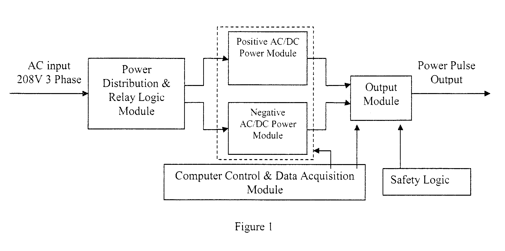
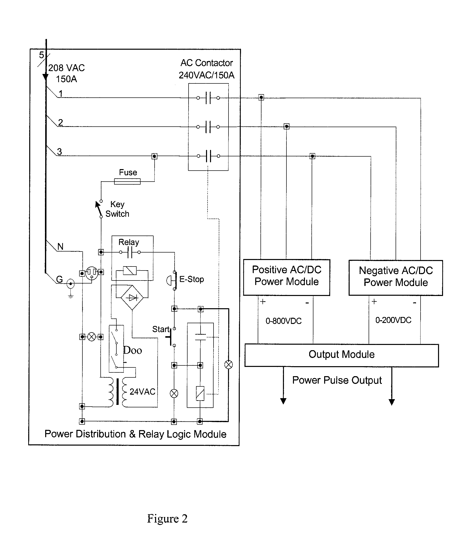
Pulsed power supply for plasma electrolytic deposition and other processes
a technology of plasma electrolysis and power supply, which is applied in the direction of pulse train generators, pulse techniques, instruments, etc., can solve the problems of no such product available on the market, difficult to use to regulate surface discharge,
- Summary
- Abstract
- Description
- Claims
- Application Information
AI Technical Summary
Benefits of technology
Problems solved by technology
Method used
Image

Examples
example 1
Ceramic Coatings on Titanium Substrates
[0064]Commercially pure titanium plate (Grade 2, R50400) and aluminum alloy plate (5052-H32) were cut into samples with a size of 50 mm×10 mm×1 mm. Zircoalloy coupons were offered by AECL, Canada, with a size of 25 mm×10 cm×1.3 mm. Prior to plasma electrolytic oxidation (PEO) treatment, the specimens were polished with 400 grit SiC abrasive paper, and degreased with acetone followed by rinsing with distilled water. A home-made pulsed power source with a power of 26.4 kW was used for PEO treatment of the samples. The unit for PEO processing mainly consists of a water-cooled glass electrolyser with stainless steel liner and a high power electrical source. The stainless steel liner also serves as the counter electrode. The electrolyte solution in this study is consisted of 27 g L−1 Na2SiO3 aqueous solution. After the treatment, the coated samples were rinsed with disionized water and dried in air.
[0065]The pulse output of the power supply unit for...
example 2
Ceramic Coatings on Aluminum Substrates
[0073]Prior to plasma electrolytic oxidation (PEO) treatment, the Aluminum substrate specimens were polished with 400 grit SiC abrasive paper, and degreased with acetone followed by rinsing with distilled water. A home-made pulsed power source with a power of 26.4 kW was used for PEO treatment of the samples. The unit for PEO processing mainly consists of a water-cooled glass electrolyser with stainless steel liner and a high power electrical source. The stainless steel liner also serves as the counter electrode. The electrolyte solution in this study is consisted of 27 g L−1 Na2SiO3 aqueous solution. After the treatment, the coated samples were rinsed with disionized water and dried in air.
[0074]FIG. 9 shows SEM images of the surface of aluminum-based ceramic coating prepared at 2700 Hz, D=20%, and R=3. It shows that the coating is relatively uniform and no cracks are found on the surface. FIG. 10 shows the XRD patterns of the coating on alumi...
example 3
Ceramic Coatings on Zirconium-based Alloy
[0075]Zircoalloy coupons were offered by AECL, Canada, with a size of 25 mm×10 cm×1.3 mm. Prior to plasma electrolytic oxidation (PEO) treatment, the specimens were polished with 400 grit SiC abrasive paper, and degreased with acetone followed by rinsing with distilled water. A home-made pulsed power source with a power of 26.4 kW was used for PEO treatment of the samples. The unit for PEO processing mainly consists of a water-cooled glass electrolyser with stainless steel liner and a high power electrical source. The stainless steel liner also serves as the counter electrode. The electrolyte solution in this study is consisted of 27 g L−1 Na2SiO3 aqueous solution. After the treatment, the coated samples were rinsed with disionized water and dried in air.
[0076]FIG. 11 shows SEM images of the surface of ZrO2 coating prepared at 2700 Hz, D=20%, and R=3. From the SEM images, the coating is relatively uniform, however, it should be pointed out th...
PUM
| Property | Measurement | Unit |
|---|---|---|
| frequencies | aaaaa | aaaaa |
| power | aaaaa | aaaaa |
| temperature | aaaaa | aaaaa |
Abstract
Description
Claims
Application Information