
Inverter device

a technology of inverter device and phase terminal, which is applied in the direction of engine-driven generators, magnetic circuit rotating parts, rotary electric machines, etc., can solve the problems of not being able to efficiently cool both capacitors and switching elements, not being optimized, and increasing the size of the electrical connection structure between the plurality of ac phase terminals of the inverter device, so as to reduce the length improve energy efficiency, and reduce the electrical resistance of the electrical connection member length

Inactive Publication Date: 2015-04-28
AISIN AW CO LTD
View PDF20 Cites 5 Cited by
  • Summary
  • Abstract
  • Description
  • Claims
  • Application Information

AI Technical Summary

Benefits of technology

[0009]Accordingly, it is desirable to optimize the disposition of respective components in an inverter device connected to a rotary electric machine as a driving power source of a vehicle so that an electrical connection structure between the inverter device and the rotary electric machine is simplified and cooling performance is secured.

Problems solved by technology

However, in this structure, an electrical connection structure between the rotary electric machine and the plurality of AC phase-terminals of the inverter device is apt to be increased in size and become complicated.
For this reason, there is a possibility that it is not possible to efficiently cool both the capacitors and the switching elements.
That is, when the performance for cooling the components (the switching elements, the capacitors, or the like) of the inverter device or the electrical connection between the inverter device and the rotary electric machine as a driving power source of the vehicle is considered, the disposition of the respective components of the inverter device disclosed in JP-A-2008-29094 is not necessarily optimized.

Method used


Image

  • Inverter device
  • Inverter device
  • Inverter device

Examples


Embodiment Construction

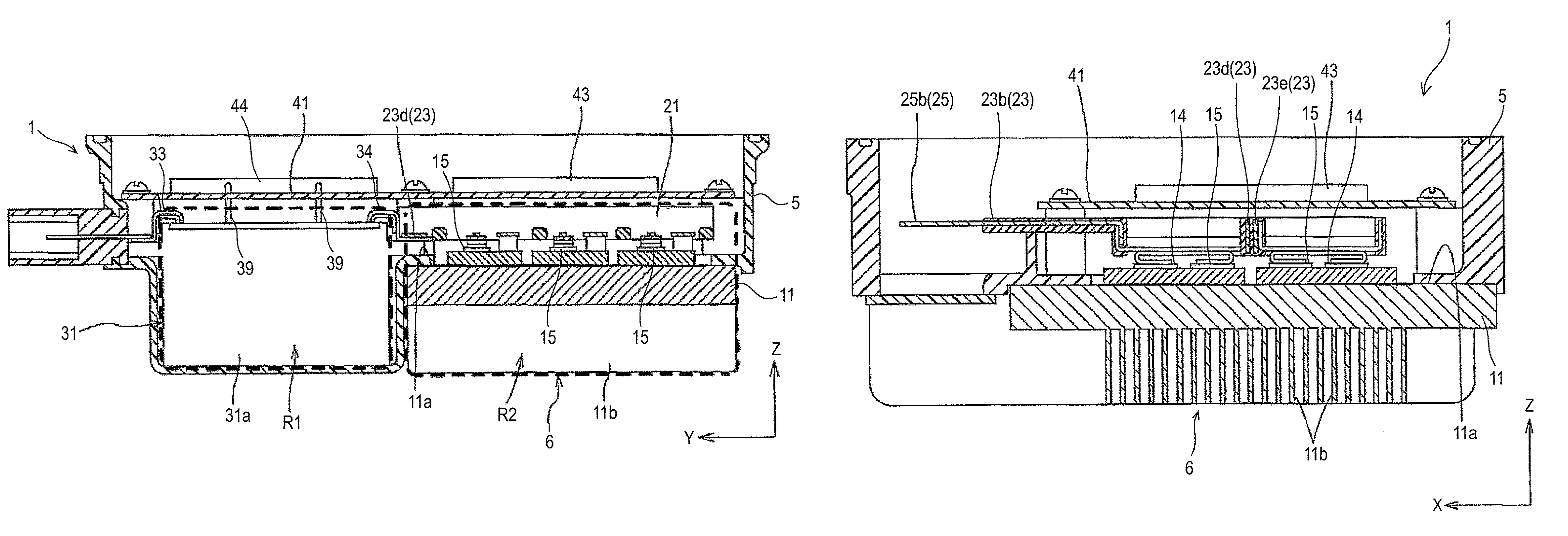
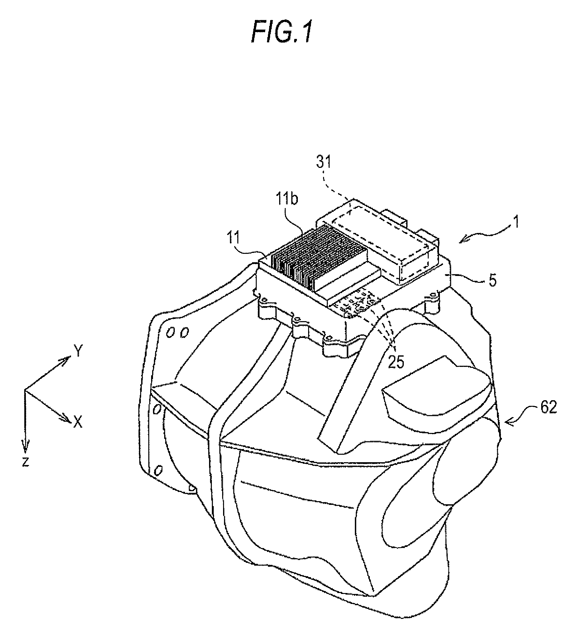
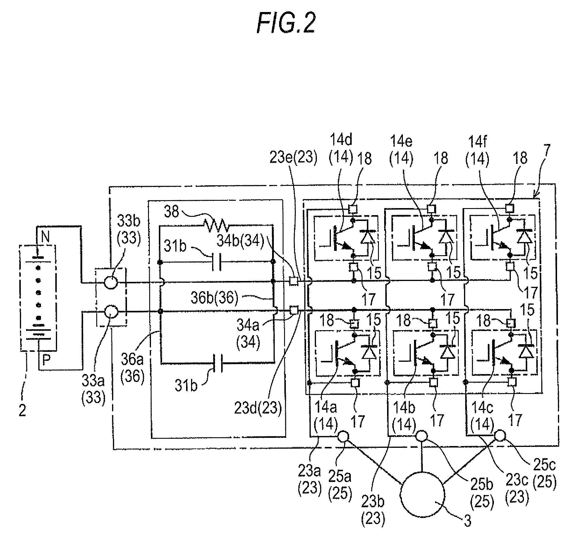
[0053]An embodiment of an inverter device according to the invention will be described with reference to the drawings. In this embodiment, an inverter device 1 of a system, which controls a rotary electric machine 3 functioning as a driving power source of for the wheels of a hybrid vehicle V (which may be simply referred to as a “vehicle V” hereinafter), will be described by way of example. As shown in FIG. 8, the hybrid vehicle V includes an internal combustion engine 61, a vehicle drive device 62 including a rotary electric machine 3, and an inverter device 1. The inverter device 1 includes an inverter circuit 7, and controls the rotary electric machine 3 that is an external device when seen from the inverter device 1. Meanwhile, in this embodiment, the rotary electric machine 3 is formed of an AC motor that is driven by three-phase alternating current. The rotary electric machine 3 can function as both a motor that is supplied with electric power and generates power and a genera...


PUM


Abstract

An inverter includes a plurality of switching elements that convert between DC and AC power. A base plate includes a surface on which the switching elements are placed. Heat dissipating fins are provided on the opposite side of the base plate. Power is input and output through AC power terminals to and from a rotary electric machine to drive a vehicle. The terminals are electrically connected to the switching elements. A capacitor smoothes the DC power. The inverter is fixed to a case of the rotary electric machine. A rotating shaft of the rotary electric machine extends in a width direction of the vehicle. The base plate is disposed adjacent to the AC terminals in the width direction. A plurality of AC phase-terminals is sequentially arrayed perpendicular to the rotating shaft. The capacitor is disposed adjacent to the heat dissipating fins on the rear side of the vehicle.

Description

INCORPORATION BY REFERENCE[0001]The disclosure of Japanese Patent Application No. 2011-080708 filed on Mar. 31, 2011, including the specification, drawings and abstract thereof, is incorporated herein by reference in its entirety.BACKGROUND OF THE INVENTION[0002]1. Field of the Invention[0003]The present invention relates to an inverter device including a plurality of switching elements that convert electric power between DC power and AC power, a base plate that includes an element placing surface on which these plurality of switching elements are placed, heat dissipating fins that are provided on the side of the base plate opposite to the element placing surface, AC terminals through which AC power is input and output to and from a rotary electric machine as a driving power source of a vehicle and which are electrically connected to the switching elements, and a capacitor that smoothes DC power.[0004]2. Description of the Related Art[0005]In recent years, a hybrid vehicle or an ele...

Claims


Application Information

Patent Timeline
Patent Type & Authority Patents(United States)
IPC IPC(8): H02K9/22H02K5/18B60L50/16H02K11/00H02M7/00H05K7/20
CPCH02M7/003H02K5/18H02K11/0073H05K7/20918H02K11/33
Inventor ITO, KOHEIKONDO, TATSUYASUZUKI, TOMOYUKI
Owner AISIN AW CO LTD
Learn More