Video tracking systems and methods employing cognitive vision

a technology of video tracking and cognitive vision, applied in the field of video object detection systems, can solve the problems of many prior art methods not performing well with video collected in uncontrolled real world scenes

Active Publication Date: 2015-04-28
INTUVISION
View PDF77 Cites 11 Cited by
  • Summary
  • Abstract
  • Description
  • Claims
  • Application Information

AI Technical Summary

Benefits of technology

[0018]At the first layer a master tracker operating at a low level of focus detects new objects appearing in a scene and triggers on the second layer, highly focused tunnel trackers dedicated for each object. The master tracker uses consecutive frame differences to perform rough object detection at each frame and does not perform object correspondence by itself, but instead relies on abstracted correspondence information generated by the tunnel trackers. The tunnel trackers track each object in a constrained small area (halo) around the object. This layered approach will provide more efficiency in terms of both accuracy and speed by separating overall coarse tracking task of master tracker from the dedicated fine tracking of individual tunnels, managing resources similar to human's object based attention. In our proposed method, due to processing in the limited area of each tunnel more reliable identification and modeling of object features (both color and texture) can be done for accurate tracking compared to both background subtraction based and object transformation or contour based methods.
[0020]Aside form the benefits described above, the tunnel vision tracker presents a natural processing hierarchy for efficient mapping of tracking tasks on one or several processors, including embodiments using dedicated processors, within various software and hardware architectures. Another important benefit of the two layer, or multilayer layer tracking approach is providing a natural framework for tracking within wide view cameras with embedded high definition views or multiple camera or view environments with multiple views provided by a camera array with overlapping or non-overlapping views.

Problems solved by technology

Many prior art methods do not perform well with video collected in uncontrolled real world scenes, where a background image with no moving object maybe hard to obtain or a robust object kernel density or a boundary contour can not be established at each frame.

Method used


Image

  • Video tracking systems and methods employing cognitive vision
  • Video tracking systems and methods employing cognitive vision
  • Video tracking systems and methods employing cognitive vision

Examples


Embodiment Construction

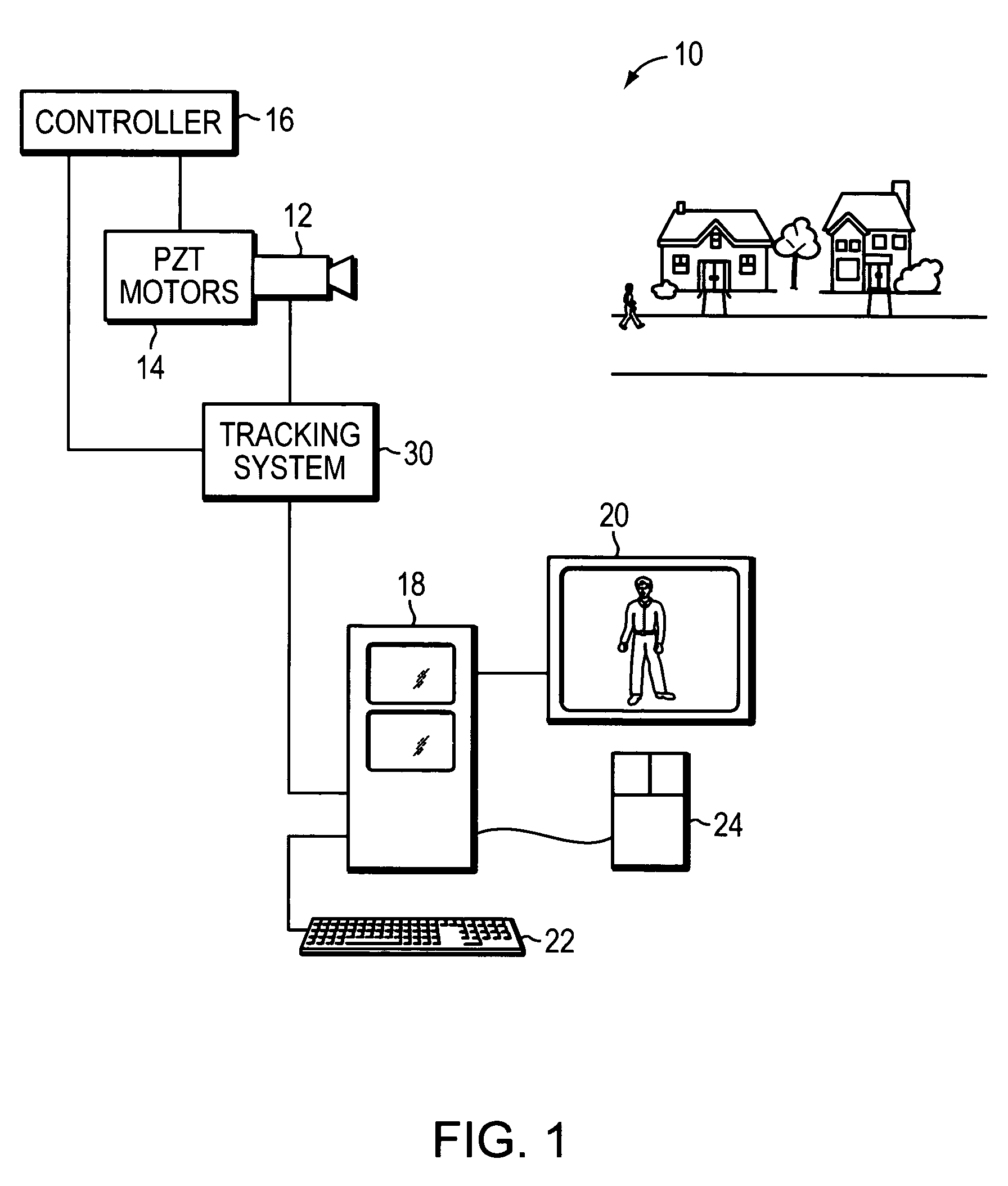
[0037]FIG. 1 illustrates schematically a video system 10 for recording video images. Video system 10 includes a camera 12 displaced by PTZ motors 14 and controlled by a controller 16. A computer 18 is connected to a computer monitor 20, keyboard 22 and a mouse 24. Tracking system 30 oversees the entire hardware operation.

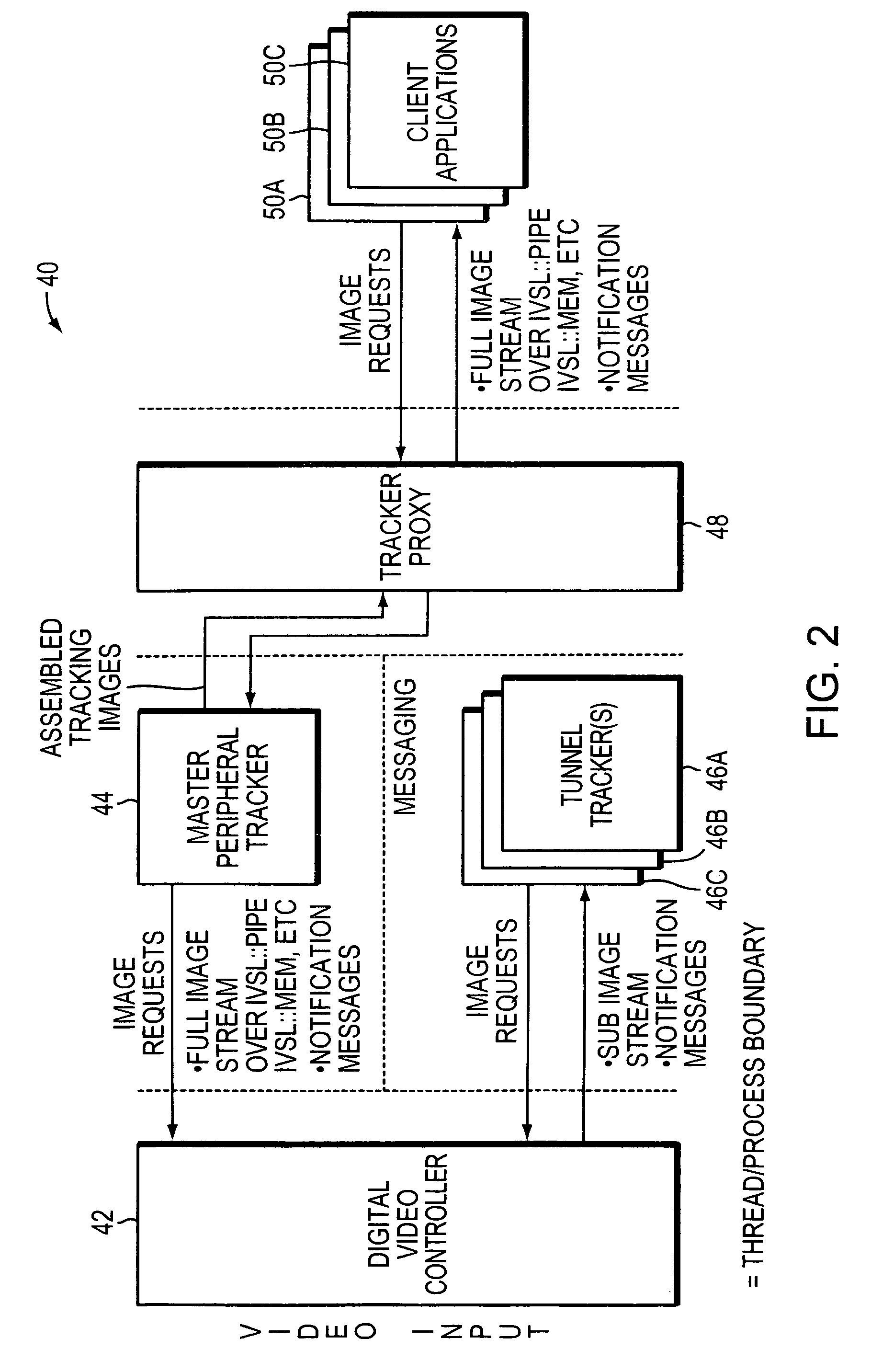
[0038]Referring to FIG. 2, a video tracking system 40 includes a digital video controller 42, a peripheral tracker 44 (i.e., a master tracker 44), tunnel vision tracker 46 (i.e., tunnel trackers 46A, 46B, 46C . . . ), and a tracker proxy 48 communicating with client applications 50A, 50B, 50C . . . . Tracker proxy 48 may include object definitions, user configurations, and user requests received from client applications 50A, 50B, 50C. Tracker proxy 48 may be eliminated in certain embodiments. Digital video controller 42 receives a video in any one of different types of formats and holds digital images. Peripheral tracker 44 sends image requests to digital video cont...


PUM


Abstract

Video tracking systems and methods include a peripheral master tracking process integrated with one or more tunnel tracking processes. The video tracking systems and methods utilize video data to detect and / or track separately several stationary or moving objects in a manner of tunnel vision. The video tracking system includes a master peripheral tracker for monitoring a scene and detecting an object, and a first tunnel tracker initiated by the master peripheral tracker, wherein the first tunnel tracker is dedicated to track one detected object.

Description

[0001]This application claims priority from U.S. Provisional Application 61 / 127,013 filed on May 9, 2008, which is incorporated by reference.[0002]The present invention relates generally to video tracking systems and methods employing principles of cognitive vision.BACKGROUND OF THE INVENTION[0003]There are different video object detection systems that facilitate the detection of events and activities of interest. Many different algorithms are frame based algorithms that require object detection at each frame and establishment of a correspondence between the object detections in consecutive frames to enable tracking; i.e., the frame and correspondence based tracking algorithms. The object correspondence between frames may be achieved by prediction filtering or particle filtering applied to object motion and appearance attributes.[0004]Many prior art methods do not perform well with video collected in uncontrolled real world scenes, where a background image with no moving object mayb...

Claims


Application Information

Patent Timeline
Patent Type & Authority Patents(United States)
IPC IPC(8): H04N5/225G01S3/786G06K9/00G06K9/32G08B13/196
CPCG08B13/196G06K9/00771G08B13/19608G06K9/3241G08B13/19652G01S3/7864G06T7/246G06T7/194G06V20/52G06V20/20G06T2207/30232G06T2207/30244G06T2210/12H04N7/183
Inventor GULER, SADIYE ZEYNOSILVERSTEIN, JASON ADAMFARROW, MATTHEW KEVINPUSHEE, IAN HARRIS
Owner INTUVISION
Why Eureka
Try Eureka