
Percutaneous modular head-to-head cross connector

a head-to-head cross connector and percutaneous technology, applied in the field of surgical screw system comprising modular head-to-head cross connectors, can solve the problems of limiting the range of spinal pathologies, increasing the likelihood that surgery may be needed to correct one or more spinal pathologies, and spinal pathologies

Inactive Publication Date: 2015-05-05
NEUROVENT
View PDF81 Cites 33 Cited by
  • Summary
  • Abstract
  • Description
  • Claims
  • Application Information

AI Technical Summary

Benefits of technology

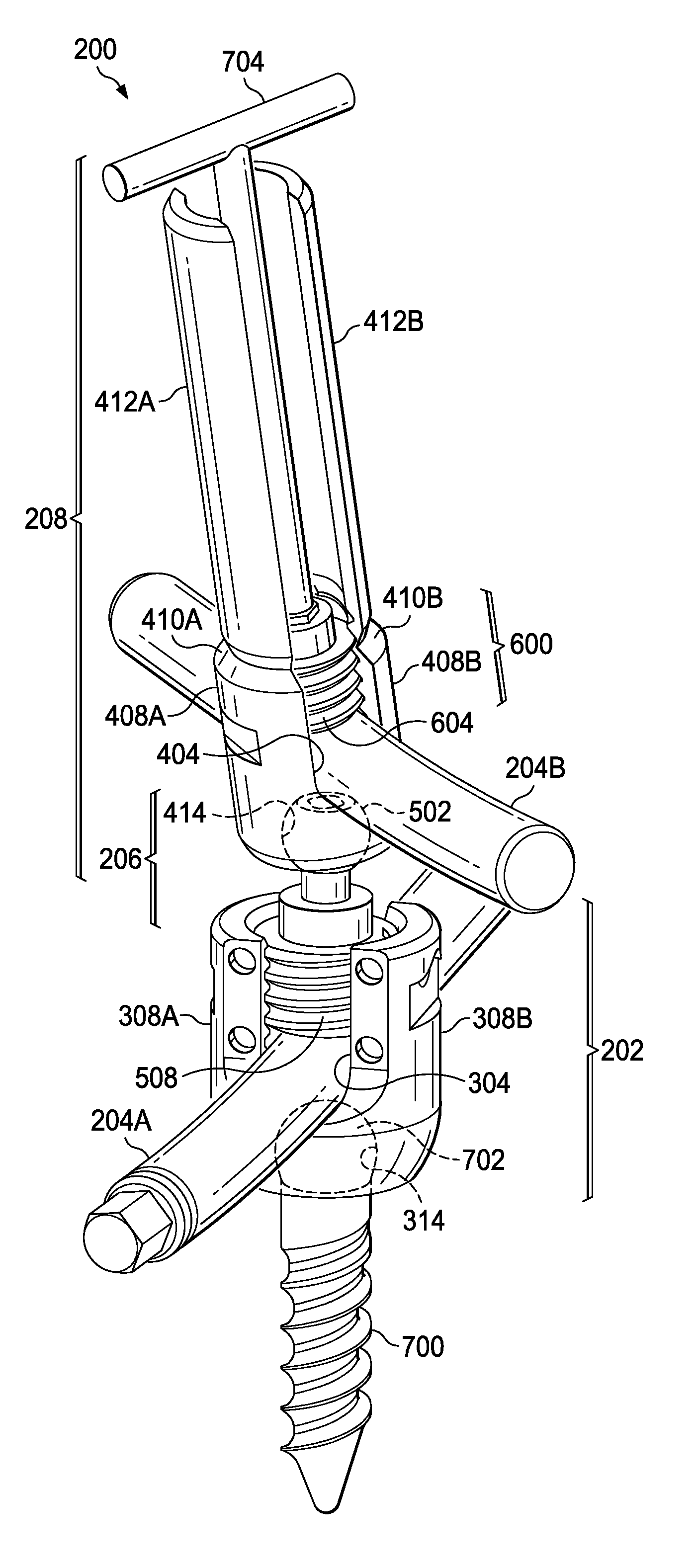
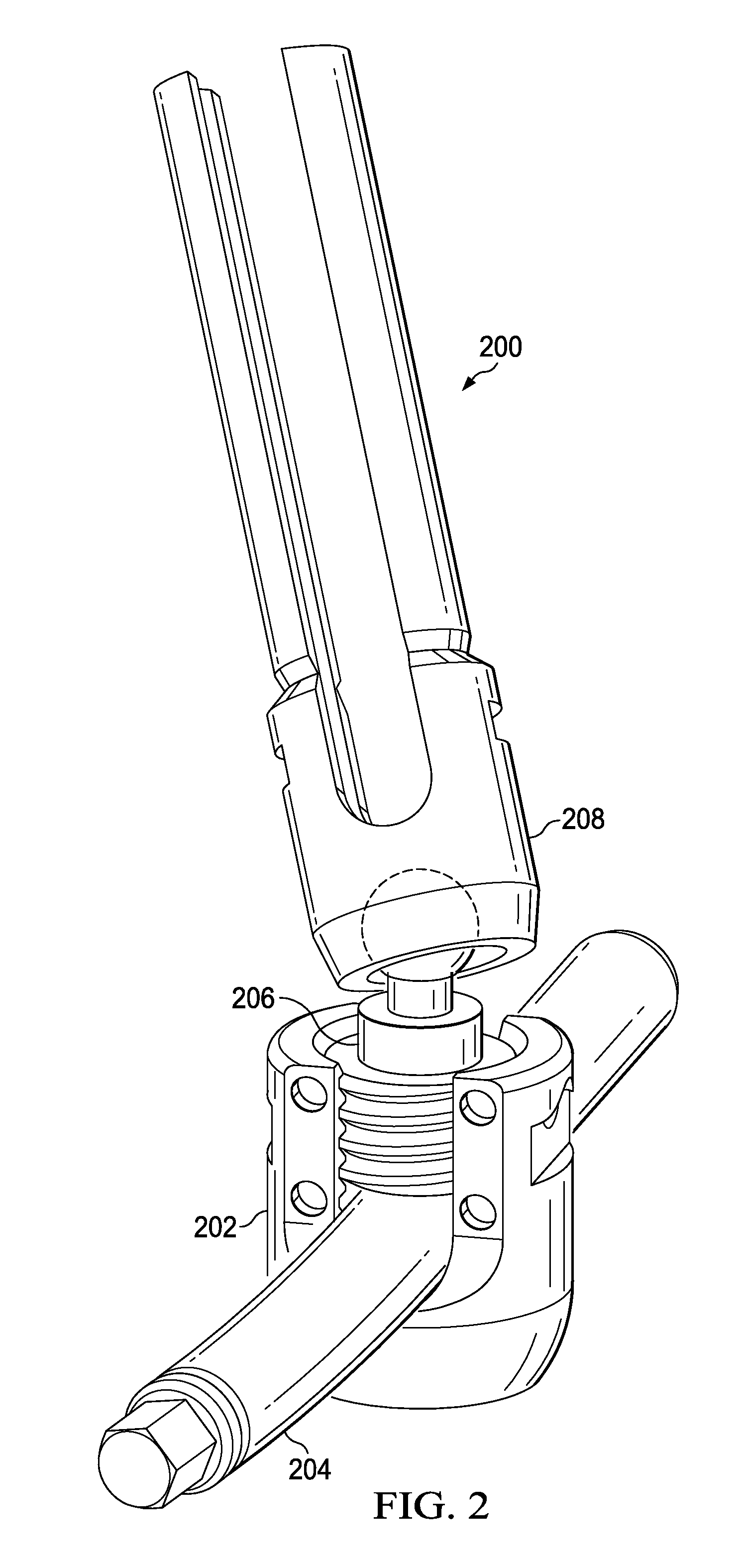
The patent describes a surgical screw system that allows for percutaneous delivery of an implantation rod. The system uses modular head-to-head cross connectors that can be combined in different ways to allow for more than two levels of rods. The system includes a fastener element, U-shaped bodies, and compression elements that work together to securely attach the rods to the bone. This system allows for greater stability and secure fixation in spinal surgery procedures.

Problems solved by technology

With its complex nature, however, there is also an increased likelihood that surgery may be needed to correct one or more spinal pathologies.
Genetic or developmental irregularities, trauma, chronic stress, tumors and disease can result in spinal pathologies that either limit this range of motion or that threaten critical elements of the nervous system housed within the spinal column.
The orientation of each of these rods, however, are often limited by the alignment of the one or more screws they are affixed to.

Method used


Image

  • Percutaneous modular head-to-head cross connector
  • Percutaneous modular head-to-head cross connector
  • Percutaneous modular head-to-head cross connector

Examples


Embodiment Construction

[0017]For purposes of describing and claiming the present disclosure, the term “interference fit” in intended to refer to physical contact between two or more components and may include a slip fit, a ball-joint fit, or similar fit between two or more components.

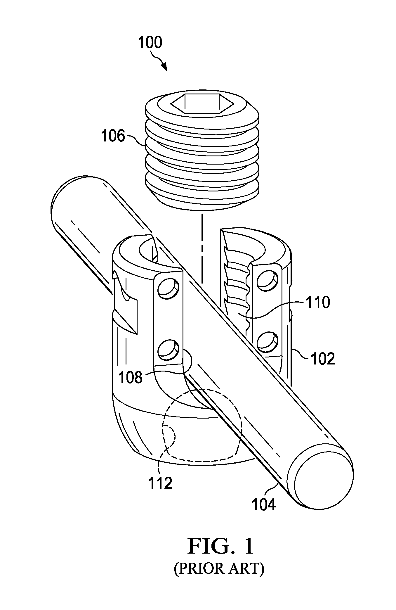
[0018]FIG. 1 depicts a prior art connection system 100 for connecting a fastener element (e.g., a pedicle screw, not shown) relative to a rod 104 for vertebral fixation. Connection system 100 may comprise a U-shaped body 102, the rod 104, and a compression element 106. The rod 104 may be shaped to fit within the U-shaped body 102 at a rod receiving channel 108 with a slip fit. After the rod 104 is received within the rod receiving channel 108, the compression element 106 may be threaded into the U-shaped body 102 and mate with internal threads 110 of the U-shaped body 102. The compression element 106 may clamp the rod 104 against an orbital head of the fastener element when the fastener element is received into an orbital rec...


PUM


Abstract

A modular head-to-head cross connector or construct extension system comprising a fastener element driven into a bone in a first orientation, a first U-shaped body operable to receive the fastener element and operable to receive a first rod in a first rod receiving channel, and a first compression element driven adjacent to and against the first rod in the first rod receiving channel, thereby engaging the first rod against the fastener element in a second orientation independent of the first orientation of the fastener element. The system further comprises a second U-shaped body operable to receive first compression element and operable to receive a second rod in a second rod receiving channel, and a second compression element driven adjacent to and against the second rod in the second rod receiving channel, thereby engaging the second rod against the first compression element in a third orientation independent of the second orientation.

Description

FIELD OF THE INVENTION[0001]The present disclosure relates to a surgical screw system comprising modular head-to-head cross connectors for use with implantation rods, and related methods of using a surgical screw system comprising modular head-to-head cross connectors with implantation rods. In an embodiment, the system may allow true percutaneous delivery through the spinous ligament.BACKGROUND OF THE INVENTION[0002]The spinal column of bones is highly complex anatomical structure that includes over 20 bones coupled to one another, housing and protecting critical elements of the nervous system having innumerable peripheral nerves and circulatory bodies in close proximity. Despite its complexity, the spine is a highly flexible structure, capable of a high degree of curvature and twist in nearly every direction. The more than 20 discrete bones of an adult human spinal column are anatomically categorized as one of four classifications—cervical, thoracic, lumbar, or sacral—and are coup...

Claims


Application Information

Patent Timeline
Patent Type & Authority Patents(United States)
IPC IPC(8): A61B17/70
CPCA61B17/7032A61B17/7037A61B17/7049A61B2090/037A61B17/00234A61B17/7002A61B17/7043
Inventor FRANKEL, BRUCESEMLER, MARK EVALDWALKER, CLINTONFEDOROV, SERGEY
Owner NEUROVENT
Learn More