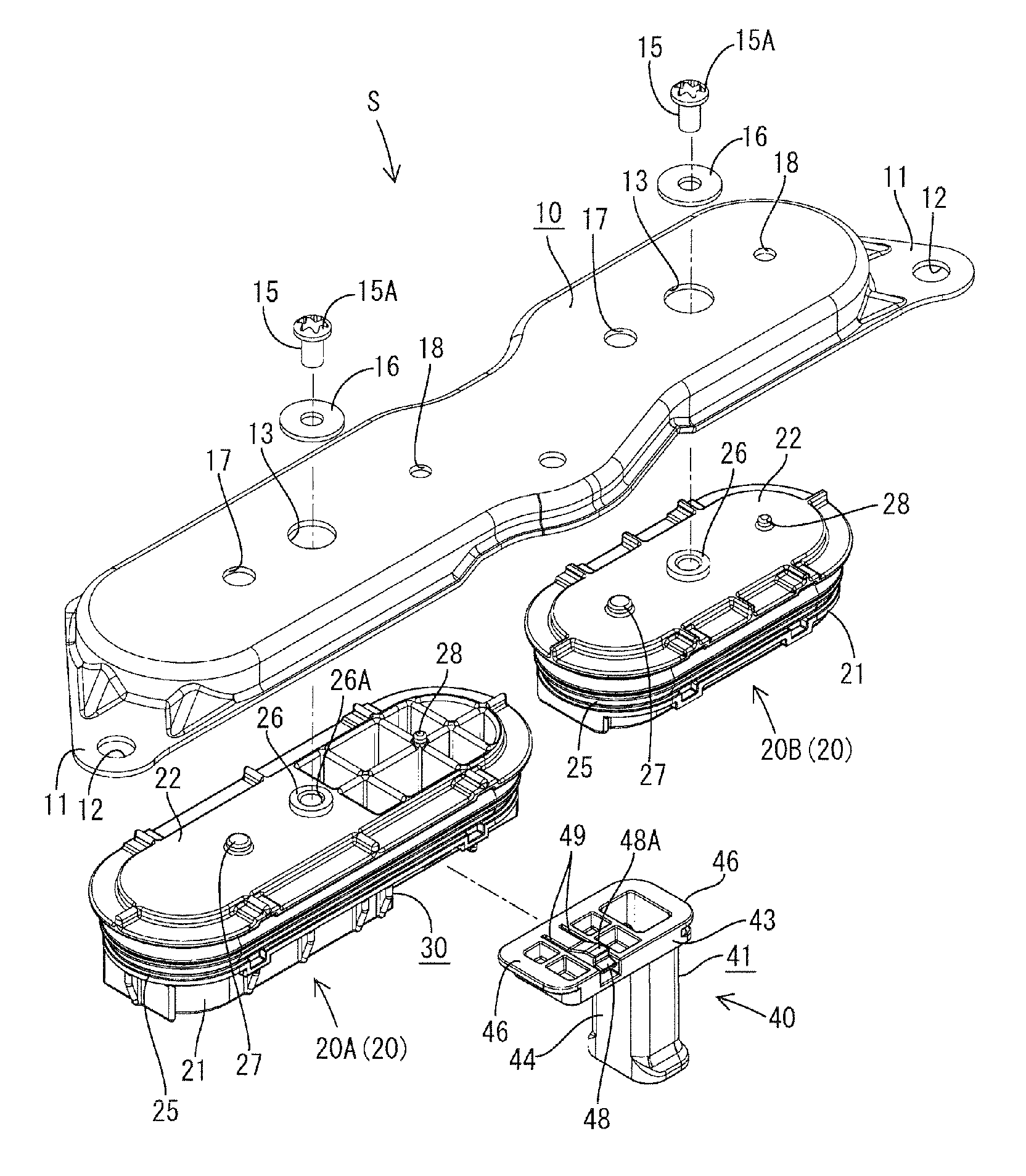

Seal cover for in-vehicle electric device

a technology for sealing covers and electric devices, applied in the direction of electrical apparatus casings/cabinets/drawers, coupling device connections, semiconductor/solid-state device details, etc., can solve the problems of uneven squeeze margin of seal ring, adversely affecting the sealing function, slow connection operation, etc., and achieve the effect of high accuracy and efficient sealing cover attachmen

Active Publication Date: 2015-05-05
SUMITOMO WIRING SYST LTD
View PDF19 Cites 16 Cited by
  • Summary
  • Abstract
  • Description
  • Claims
  • Application Information

AI Technical Summary

Benefits of technology

The invention is related to a seal cover for a case, which has an interlock connector and a waiting connector for connecting to an external device. The interlock connector is designed to be able to move in different directions, allowing for easy connection to the waiting connector with high accuracy. It also allows for a uniform sealing ability over the entire circumference of the case opening. A simple structure is used for the interlock connector, including only one resilient locking piece, which can achieve a floating function. The seal ring holder and the case opening can be fitted perfectly, ensuring a uniform sealing ability. The invention also includes a pin and a restricting hole to prevent errors in the mounting and rotational displacement of the seal ring holder.

Problems solved by technology

However, the connecting operation is slower because of the forcible connection of the interlock connector and the waiting connector when the fitting of the seal cover is fit into the opening.
Further the fitting may be displaced as the interlock connector and the waiting connector are connected thereby making a squeeze margin of the seal ring uneven and adversely affecting the sealing function.

Method used


Image

  • Seal cover for in-vehicle electric device
  • Seal cover for in-vehicle electric device
  • Seal cover for in-vehicle electric device

Examples


Embodiment Construction

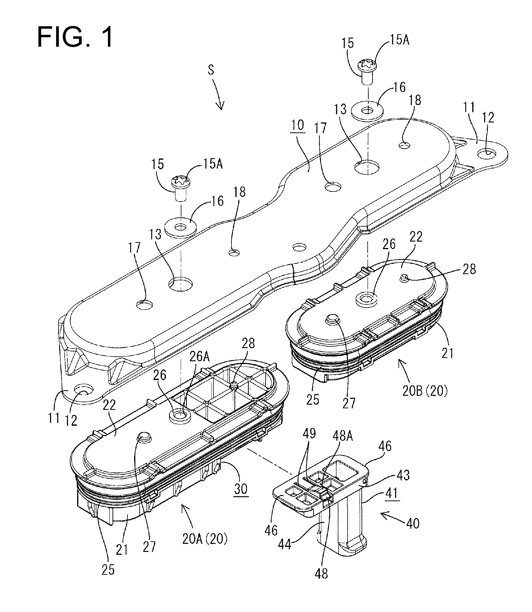
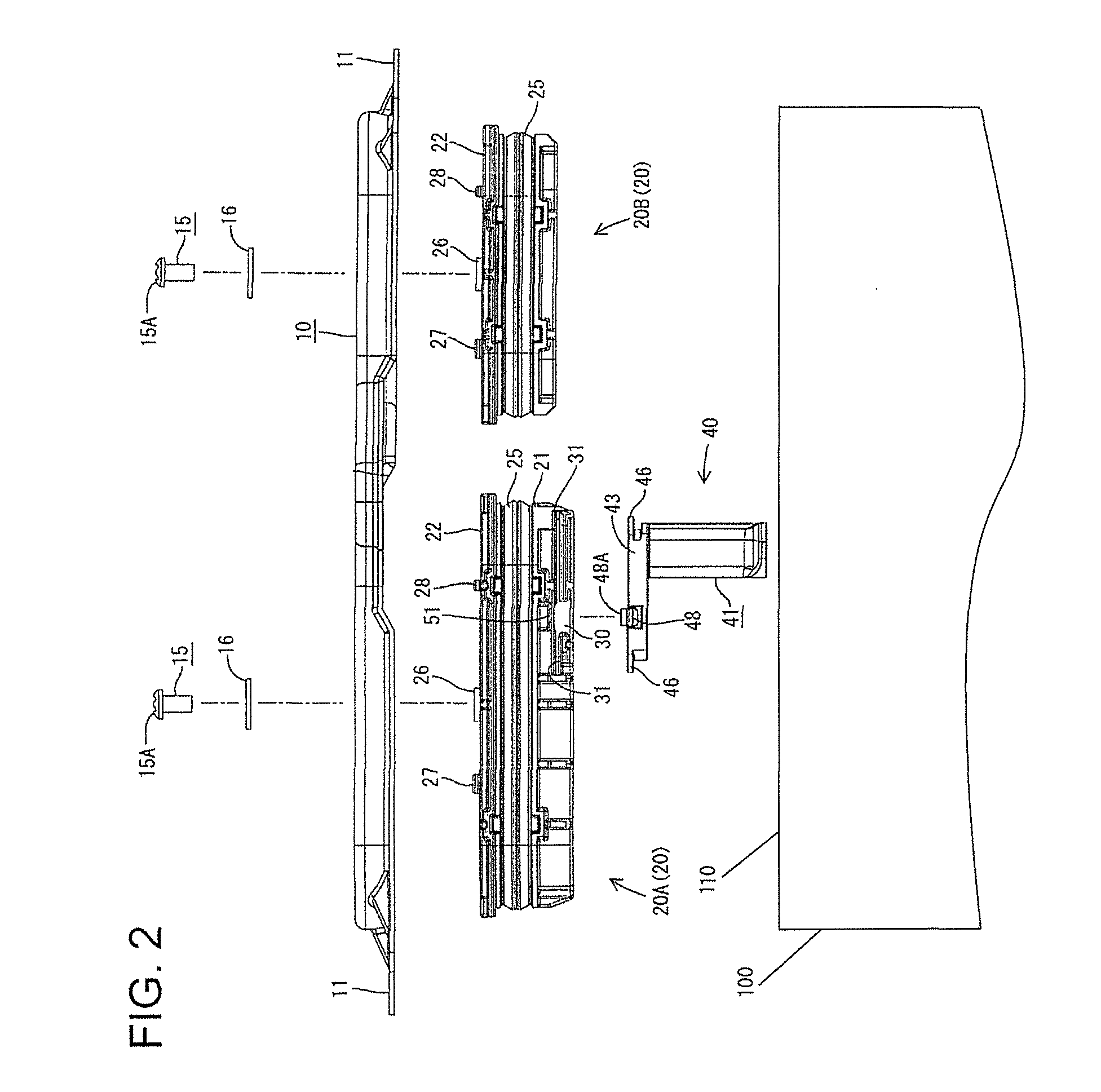
[0037]A seal cover in accordance with an embodiment of the invention is provided for simultaneously closing two juxtaposed work openings 110 in one surface of an a shield case 100 that houses an electric device. Further, an interlock mechanism is provided that sets an electric member (such as a circuit) in a specified electric state, e.g. turns on and off an energizing circuit for the electric device, as this seal cover is attached and removed. Although not shown, a waiting connector accommodating two contact terminals drawn out from the electric member (e.g. the energizing circuit) is mounted on a terminal block in the case.

[0038]As shown in FIG. 1, the seal cover S includes a cover main body 10, two seal ring holders 20 and an interlock connector 40.

[0039]The main body 10 is formed by press-working a conductive plate, such as a steel plate, and defines a long narrow substantially elliptical inverted shallow saucer capable of covering the both openings of the case. Specifically, th...


PUM


Abstract

A seal cover includes a cover main body (10) shaped to cover an opening of a case and to be attached to a surface of the case. A seal ring holder (20A) is on the underside of the cover main body (10) and is arranged to fit into the opening. A seal ring (25) is on the outer peripheral surface of the seal ring holder (20A) and closely contacts the inner peripheral surface of the opening. An interlock connector (40) projects from the seal ring holder (20A) for connecting to the waiting connector and sets an energizing circuit in an energized state or a non-energized state upon being connected to or separated from the waiting connector. The interlock connector (40) is mounted on the seal ring holder (20A) to be movable in a direction perpendicular to a connecting direction to the waiting connector.

Description

1. FIELD OF THE INVENTION[0001]The invention relates to a seal cover to be removably attached to close an opening such as a work opening provided in a case of an in-vehicle electric device.2. DESCRIPTION OF THE RELATED ART[0002]An electric vehicle is likely to have a device mounted in a case. The case typically has an opening for accessing internal connectors, and a seal cover or service cover is attached to the opening. U.S. Patent Application Publication No. 2010 / 0255728 discloses a conventional seal cover with a main body capable of covering an opening. A fitting on the underside of the main body and can fit into the opening and locking pieces are provided to engage the opening. A seal ring is mounted on the outer peripheral surface of the fitting and closely contacts the inner peripheral surface of the opening to provide sealing when the seal cover is attached to the opening. Thus, water and external matter cannot enter through the opening.[0003]An operation position in the case...

Claims


Application Information

Patent Timeline
Patent Type & Authority Patents(United States)
IPC IPC(8): H01J5/00H05K5/06H01R13/627H01R31/08H01R29/00H01L23/48H05K5/00H01R13/46H01J15/00H01R13/52H01R13/631H01R13/70H01R31/06
CPCH01R13/5202H01R13/5213H01R13/701H01R31/06H01R13/6315
Inventor SAKAKURA, KOUJI
Owner SUMITOMO WIRING SYST LTD
Learn More